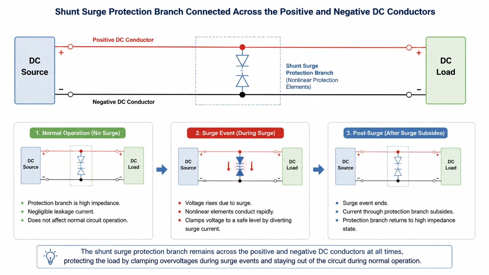
A DC surge protection circuit limits a brief overvoltage by providing a temporary conducting path across the conductors being protected. In normal operation, that protection branch conducts little current. During a surge, its nonlinear components conduct strongly and limit the voltage. After a surge within the circuit’s capabilities, the branch returns to its normal state. If a component becomes damaged or overheated, a separate disconnection function may need to remove it from service.
The important distinction is between limiting voltage during a transient and interrupting a sustained fault afterward. Understanding both functions helps you interpret a DC SPD diagram without assuming that an SPD, fuse and circuit breaker do the same job. This guide follows the operating principle; actual connections and component ratings remain specific to the equipment and DC system.
Three Operating States of a DC Surge Protection Circuit
Start with a DC source supplying a load through its normal supply and return conductors. A shunt protection branch connects across the pair of electrical points whose voltage needs limiting. It is an additional path, so the load current does not normally pass through the surge-limiting element itself.
As NEMA’s explanation of SPD operation describes, nonlinear components allow the protector to divert surge current while limiting voltage. The protected voltage does not become zero: a residual voltage remains during conduction.
State
Protection branch behavior
What it means for the load
Normal supply
High impedance at the intended operating voltage, with component-dependent leakage
The ordinary source-to-load path supplies power
Transient overvoltage
Nonlinear elements conduct surge current and limit the voltage across their protection path
The input still sees a transient, but its magnitude is reduced
Recovery after a tolerable surge
Conduction subsides as the transient ends
Normal operation can continue if the protector and equipment remain serviceable
This sequence describes intended operation, not a promise that every lightning event will be survived. The useful question is whether the complete assembly has been tested for the relevant surge duty and whether the resulting voltage is acceptable for the protected equipment.
Also distinguish a schematic’s electrical branches from the product’s physical terminals. An assembly may use feed-through terminals while its suppression element still operates in shunt. Use the manufacturer’s internal and connection diagrams to interpret it; the site’s DC SPD wiring guide covers the separate installation task.
Which Voltage the Circuit Protects: Differential and Common Mode
Voltage is always measured between two points. Saying that a circuit “removes a surge” is incomplete unless those points are identified. A DC input has a voltage between positive and negative, and each conductor can also have a voltage relative to the equipment’s bonding or earth reference.
Differential Mode: Voltage Between the DC Conductors
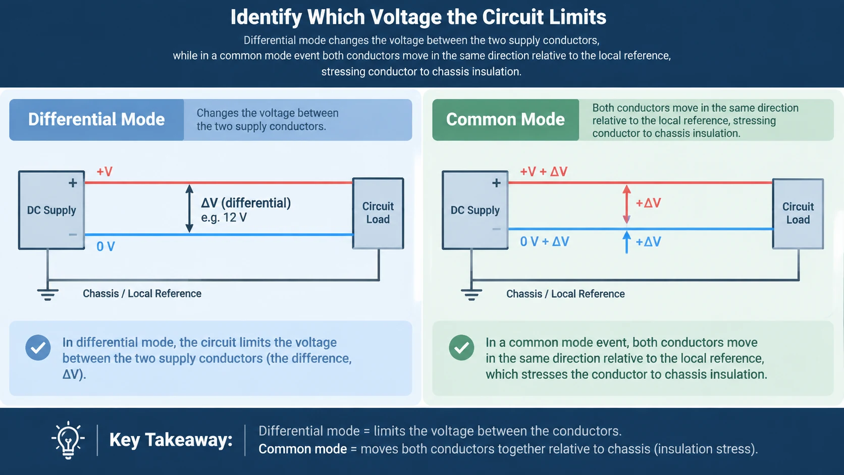
A differential-mode transient changes the voltage between the two supply conductors. A protection path across that pair limits the voltage difference seen by the input. The surge current path is between conductors; it need not be a direct path to earth.
For a purely illustrative example, imagine a nominal 24 V input. If the positive conductor briefly rises relative to the negative conductor, the input can experience a differential overvoltage. The label “24 V” alone tells you neither the size of the transient nor the required clamping voltage.
Common Mode: Voltage Relative to a Shared Reference
In a common-mode event, both supply conductors can move in the same direction relative to the local reference. Imagine their instantaneous potentials are 1,024 V and 1,000 V relative to that reference. Their difference is still 24 V, yet conductor-to-chassis insulation can be highly stressed. These invented values only illustrate voltage relationships; they are not test levels or design limits.
A protector across positive and negative alone does not establish protection for every conductor-to-earth voltage. Conversely, a multipole assembly may provide several protection paths through its internal network. Identify the declared modes and their protection levels rather than guessing from the number of cartridges.
Conceptual voltage references, not an installation diagram. Earth, chassis and DC return connections must follow the actual system design.
The Phoenix Contact fundamentals guide presents different DC protection arrangements for grounded and ungrounded systems. That is why a generic drawing cannot authorize bonding a floating DC conductor to earth.
Components Inside the Protection Branch
The label “DC surge protection circuit” can describe a small electronic input circuit or a complete power-system SPD. Both use nonlinear behavior, but their components, fault handling and intended applications can differ substantially.
Metal oxide varistor (MOV): a voltage-dependent component whose current rises sharply as its applied voltage increases. It provides a limiting characteristic rather than an ideal fixed-voltage clamp.
Transient voltage suppressor (TVS): a semiconductor protection component used in many electronic circuits. Its working voltage, breakdown voltage and clamping voltage are different specifications.
Gas discharge or gap-based element: a voltage-switching component that becomes conductive after sparkover. Its ability to stop conducting after the event depends on the component and surrounding circuit.
Do not treat a bare component as equivalent to a tested DIN-rail assembly. An assembly also has terminals, insulation, thermal behavior, monitoring and fault-disconnection arrangements. A collection of individually rated components does not automatically establish the performance of the finished unit — which is why the surge protection devices used in PV, battery and DC bus applications are specified as complete, tested assemblies.
For electronic inputs, Texas Instruments’ surge-diode selection guide explains why working and clamping voltages must be considered separately. A part that tolerates the normal DC supply may still let the protected input rise too high during its specified surge current. Checking only the voltage printed in a product name misses that distinction.
Why DC Fault Disconnection Needs Its Own Design
Normal surge diversion should be brief. A damaged protection element that continues conducting from the DC source presents a different problem: now the source can feed a sustained fault. The circuit needs a way to manage that condition without assuming the surge itself will end it.
Thermal Disconnection vs Overcurrent Protection: Two Different Jobs
Thermal protection responds to heating associated with a protection component. Overcurrent protection responds according to its current-time behavior and interruption capability. These functions may be integrated or coordinated externally, but neither should be inferred from the other.
Littelfuse’s thermally protected varistor application note explains how sustained abnormal voltage can overheat an MOV and why a thermal disconnect is useful. Its AC application examples explain the mechanism; they do not establish that those components or arrangements are suitable for a DC installation.
Whether a separate backup fuse or breaker is needed depends on the SPD’s instructions and the actual source conditions. Avoid a universal “always required” or “never required” rule. Use the site’s SPD backup fuse or circuit breaker guide for that coordination question.
How the DC Source Changes the Fault Problem
A battery-fed circuit and a PV string can present very different available fault currents. Phoenix Contact’s DC guidance calls for considering both minimum and maximum prospective short-circuit current, along with source type. A design must handle the highest relevant fault current while still detecting or disconnecting lower fault currents that could persist.
After a protection branch disconnects, the main load may remain powered, depending on the assembly. Continued inverter or equipment operation therefore does not prove that surge protection remains available. Interpret the manufacturer’s indication and alarm functions; the guide to SPD status indicators explains that separate check.
Protector Voltage vs Equipment Voltage: Why They Are Not the Same
The SPD’s specified voltage protection level describes performance under defined test conditions. The voltage appearing at the equipment also depends on the installation. Interconnecting conductors can contribute additional voltage during rapidly changing surge current.
Phoenix Contact’s surge-protection basics explains the inductive relationship u = L × di/dt. It helps explain why a conductor that carries ordinary DC current satisfactorily can still develop a substantial transient voltage when current changes quickly.
As a hypothetical arithmetic example, an effective inductance of 1 microhenry with a current rise of 1 kiloampere per microsecond produces 1 kilovolt of inductive voltage. This does not assign an inductance to a particular wire length or predict an installed protection level. It illustrates why component data and the current path must be reviewed together.
The practical implication is to request the relevant connection guidance and equipment withstand information as well as the SPD datasheet. A high surge-current rating alone does not answer how much voltage reaches the load. The site’s SPD specification terms guide distinguishes the ratings used in that review.
How to Review a DC SPD Circuit Description Before Approval
A useful protection description should let you trace what happens before, during and after an event. If a supplier provides only a product photo and one voltage rating, ask for the missing circuit information before accepting the concept.
Where does normal load current flow? Identify the main supply path separately from the surge-limiting branch.
Which voltage differences are protected? List the declared conductor-to-conductor and conductor-to-reference modes.
What does the equipment experience during the surge? Review limiting performance under the relevant test conditions and the installation guidance.
How does the branch recover or disconnect? Obtain the specified behavior after a tolerable surge and after a component fault.
What evidence matches the source? Confirm that the assembly and any backup protection are documented for the actual DC application.
These questions separate an explanation of the principle from a design ready for use. They also make technical discussions more precise: “the SPD conducts” is only part of the answer; the protected mode, remaining voltage and eventual recovery matter too.
Once those operating details are clear, use the DC surge suppressor selection guide to organize the next specification review for your application.
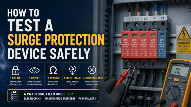
A practical field procedure for testing a surge protection device: safe isolation, visual checks, resistance and leakage measurements, how to read the results, and the limits of on-site testing.
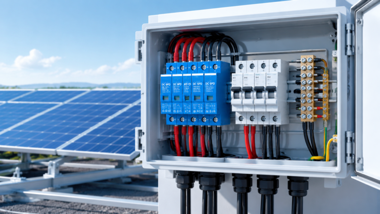
Most solar DC distribution boxes (DCDBs) are fitted with a Type 2 DC surge protection device (SPD), rated for 8/20 µs surge currents; a Type 1+2 DC SPD is required when the DC circuit is exposed to direct lightning strikes or the site has no external lightning protection system. This guide explains how to decide […]
How to wire and install a Type 2 DC surge protection device on a PV system: terminal connections, parallel wiring, backup fuse or MCB, earthing and common mistakes.