How to Match a DIN Rail Fuse Holder to the Right Fuse Link
Published: Author: Rachel
What “matching” a fuse holder actually means
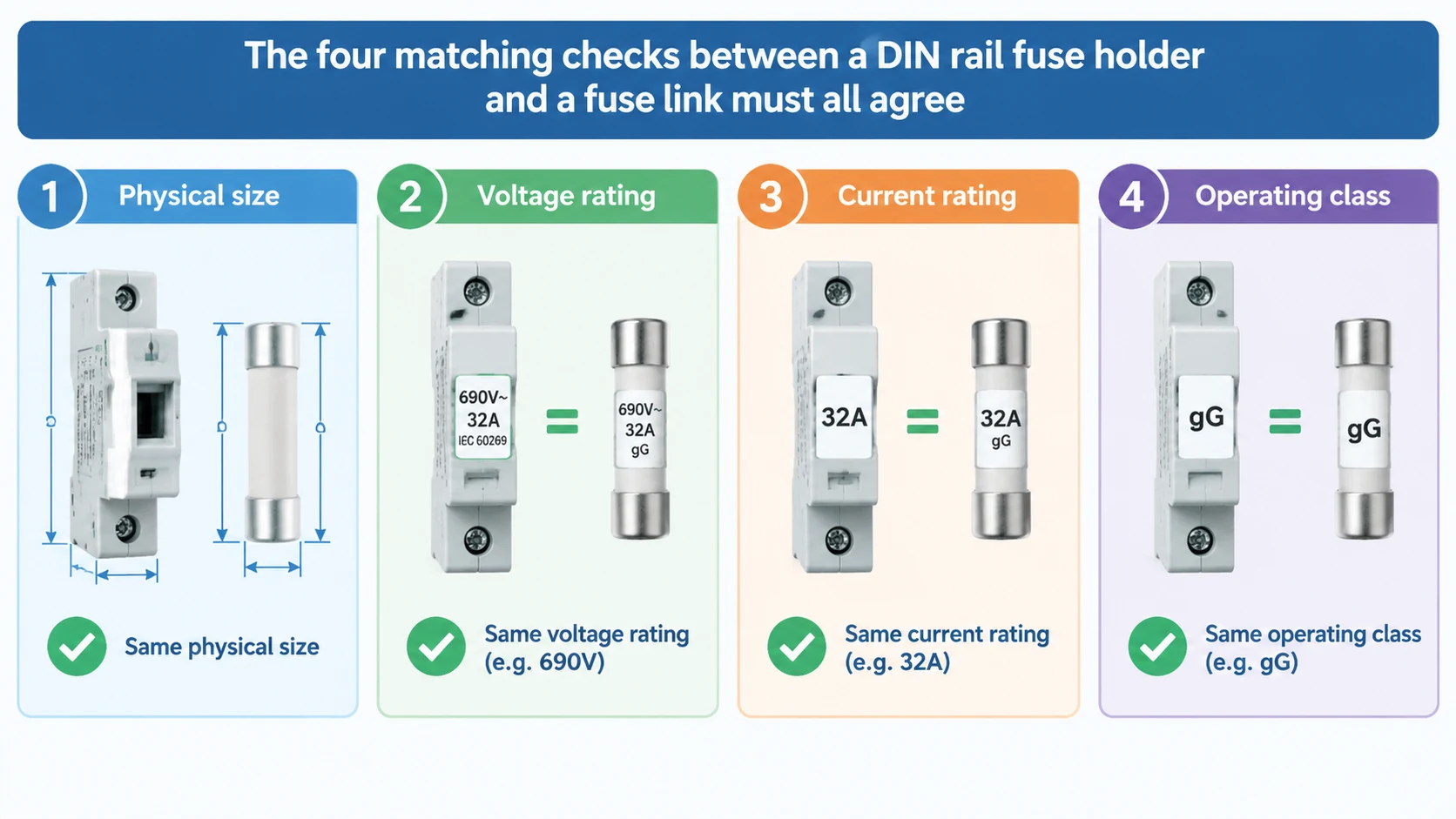
A DIN rail fuse holder is matched to a fuse link when four things agree: physical size, AC or DC voltage rating, current rating and operating class. Size agreement is the one everybody checks, because it is the one that is immediately visible. The other three are the ones that decide whether the pair will interrupt a fault, and they are the reason a holder that fits can still be the wrong holder.
Two rules frame everything below. First, the assembled pair performs to the lower of its two ratings — a 63 A fuse link in a 32 A holder is a 32 A protection system, not a 63 A one. Second, a matching physical footprint proves nothing about voltage. A 10×38 mm AC holder and a 10×38 mm PV holder look the same on a DIN rail and are not interchangeable.
The four checks, in the order that matters
Check
What must agree
Failure mode if it does not
Physical size
Fuse link body diameter and length match the holder’s contact spacing
Holder DC or AC rating at or above the circuit’s worst-case voltage
Arc may not extinguish when the fuse operates
Current rating
Holder rated current at or above the fuse link’s rated current
Holder overheats under normal load; terminals discolour
Operating class
Holder intended for the link’s class — gG, aM or gPV
Protection behaviour does not match the circuit’s fault profile
Work them in this order because the first check narrows the field fastest, and the last check is the one that most often eliminates an otherwise plausible candidate.
Check 1: size and contact geometry
Cylindrical DIN rail holders are built for one body size each. The RT18 family covers the three standard AC sizes in separate models — RT18-32 for 10×38 mm links up to 32 A, RT18-63 for 14×51 mm links up to 63 A, and the larger RT18-125 frame for 22×58 mm links up to 125 A. Within a family the holders look alike from the front, which is exactly why someone in a hurry can pick the wrong one off the shelf.
The contact geometry matters as much as the dimensions. A fuse link that is the correct nominal size but sits loosely in the carrier makes intermittent contact, and intermittent contact means resistance, heat and eventually a fuse that operates with nothing wrong in the circuit. If a link does not seat with a firm, positive fit, the holder is not the right one — forcing it is not a solution.
Check 2: the AC or DC voltage rating
This is the check that gets skipped, and it is the one with the most serious consequences. Direct current has no zero crossing, so the arc that forms inside a fuse when it operates has nothing to help it extinguish. A holder built for AC service does not have the contact separation or arc-handling design that a DC holder needs, and at higher DC voltages a fuse that clears cleanly in AC service may not clear at all.
The practical rule is short: a fuse holder must carry a DC voltage rating at or above the circuit’s maximum DC voltage, and an AC rating is not a substitute for it. A 690 V AC holder is not a 690 V DC holder. For photovoltaic work this means using a purpose-built PV holder — the same reason AC and DC fuse links of the same size are not interchangeable.
Equally, a holder rated below the system voltage is unsafe regardless of the fuse link inside it, because the holder’s own contacts must withstand the arc voltage when the fuse operates.
Check 3: current rating and the weakest-component rule
Holder rated current must be at or above the fuse link’s rated current. The reverse — a fuse link rated above its holder — is the classic error, because the link looks like an upgrade and the holder becomes the weakest part of the circuit. A 32 A holder carrying a 63 A link will run hot long before the fuse operates, and the heat is generated in the holder, not the fuse.
Holder documentation usually recommends conductor cross-sections to go with each rating, commonly in the region of 6 mm² for a 32 A holder, 16 mm² for 63 A and 35 mm² for 125 A. Treat those as the holder manufacturer’s guidance for its own product rather than a universal rule, and confirm the terminal will accept your actual conductor. Undersized wiring in a correctly rated holder produces the same heat signature as an undersized holder.
Terminal torque belongs in this check too. A correctly rated holder with a loose terminal screw generates local heat that raises the fuse’s operating temperature, and the symptom — a fuse that operates for no apparent reason — points at the fuse rather than at the connection that is actually causing it.
Check 4: operating class
Fuse class describes the fault profile the link is designed to interrupt, and the holder has to be suitable for that class:
gG — general-purpose, full-range. Standard AC distribution and cable protection.
aM — partial-range, for motor circuits. Requires separate overload protection to be complete.
gPV — photovoltaic, full-range, tested to IEC 60269-6 for PV duty including reverse feed and thermal cycling.
The class matters at the holder because the holder’s contacts and clearances are part of the interrupting path. A gG link in a PV string leaves the circuit protected by a device tested to a different duty profile, and a gPV link in an AC distribution holder loses its DC voltage rating even if the size is right.
Matching table: AC fuse links and DIN rail holders
Fuse size
AC fuse link
DIN rail holder
Typical rating
Typical application
10×38 mm
RO15, gG
RT18-32 / GD18-32
Up to 32 A, 500 V AC
Control circuits, small distribution boards
14×51 mm
RO16, gG
RT18-63
Up to 63 A, 500 V AC
Distribution and control panels
22×58 mm
RO17, gG
RT18-125
Up to 125 A, 500 V AC
AC main distribution
The pattern here is a one-to-one relationship between link family and holder model. There is no cross-size compatibility, and no model in the range accepts two sizes.
One detail worth noting in the last row: the GDPV-50 series accepts both 10×85 mm and 14×85 mm links in the same 85 mm length, and offers different mechanical versions — a standard holder, a version with status indication, and a front-operating version for installations where panel space and access matter. Two links of different diameter in the same length is precisely why the diameter has to be confirmed rather than assumed from the length.
All the matched AC and DC pairings, including the sizes covered above and the fuse link range that goes with each, are listed together on the matched fuse and fuse holder range.
Symptoms of a mismatched pair
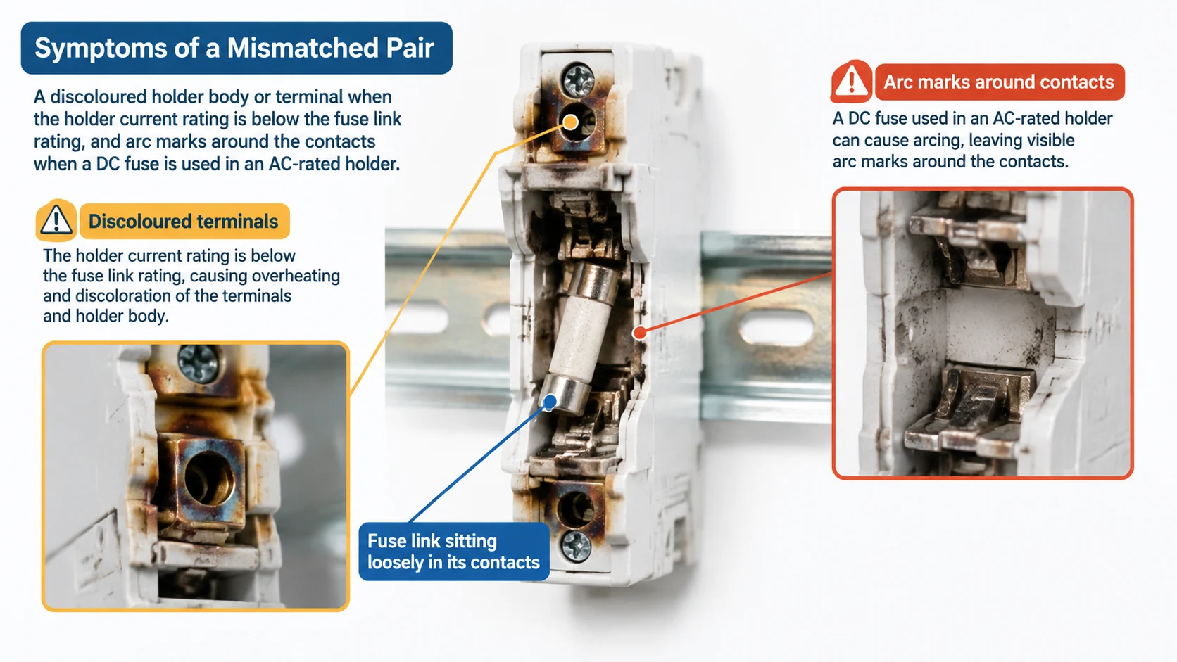
Mismatches rarely announce themselves at installation. They surface weeks later as one of a small number of symptoms, and the symptom usually points at the wrong component.
Symptom
Likely cause
What to check
Fuse operates repeatedly at normal load
Holder overheating, or derating not applied for enclosure temperature
Holder current rating against link rating; terminal torque; ambient temperature and the link’s derating curve
Holder body or terminal discoloured
Holder current rating below the fuse link’s rating
Both ratings on the datasheets — the holder is the usual limit
Arc marks or pitting around the holder contacts
DC service in an AC-rated holder, or voltage rating below system voltage
Holder DC voltage rating against worst-case circuit voltage
Fuse link sits loosely or falls out
Wrong body size for the holder
Measure the link; compare against the holder’s accepted size
Holder noticeably hotter than neighbours
Undersized conductor, loose terminal, or holder rated below the load
Conductor cross-section against the holder’s recommendation; terminal torque
One fuse in a three-phase group operates, motor continues running
No blown-fuse indication, so single-phasing goes unnoticed
Whether an indicator version of the holder would suit the panel
Every row in that table is an installation problem rather than a fuse problem, which is why replacing the fuse a second time rarely fixes anything.
What to check on the holder’s own datasheet
Before ordering, confirm these values are stated for the specific holder model rather than assumed from the series:
Accepted fuse link size or sizes
Rated current and rated AC or DC voltage
Intended operating classes
Mounting standard — most cylindrical holders clip to a 35 mm DIN rail under EN 60715
Terminal conductor range and tightening torque
Operating temperature range and any required derating
Whether an indicator or striker version is needed
An 18 mm per pole width is common for this family, which is worth knowing when counting how many circuits will fit alongside the rest of the panel equipment. Multi-pole versions group two, three or four poles in one assembly for three-phase circuits, but each moulding still accepts one fuse size only — grouping changes how circuits are arranged, not what fits.
When a DIN rail holder is not the right choice
The cylindrical DIN rail family covers a large share of control and distribution work, but it is not universal. Three situations call for something else:
High currents. Above the 125 A range the cylindrical formats give way to blade-type NH/NH00 systems. The holder geometry is entirely different.
Switching duty. A fuse holder is not a switch. It is not designed to make or break load current, and using one that way damages the contacts. Where a circuit needs to be opened under load, a dedicated fuse switch disconnector combines both functions.
Front-of-panel access. Where the fuse must be replaced from outside the enclosure, a panel-mount holder is the appropriate choice. The mounting types and what each suits are set out in the guide to what a fuse base is and how the mounting types differ .
Frequently asked questions
Can I use any 10×38 mm fuse holder with any 10×38 mm fuse link?
No. The size is one of four things that must agree. The holder also has to match the link’s AC or DC voltage rating, carry a current rating at or above the link’s, and be intended for the link’s operating class. A 10×38 mm AC holder is not suitable for a 1000 V DC gPV link.
What happens if the fuse link is rated higher than the holder?
The holder becomes the limiting component. It will run hotter than intended under normal load, terminals discolour over time, and the circuit is protected at the holder’s rating rather than the fuse’s — which is often lower than the circuit requires.
How do I know whether a holder is AC or DC rated?
Read the holder’s marked rating and its datasheet. Holders built for DC service state a VDC rating; PV holders additionally reference the gPV class of the links they accept. If only an AC rating is stated, treat the holder as AC-only.
Can a DIN rail fuse holder be used as a switch?
No. Fuse holders are not designed to make or break load current, and operating one under load damages the contacts. Use a fuse switch disconnector where switching and isolation are required.
Does a multi-pole holder accept different fuse sizes in each pole?
No. A multi-pole assembly is built around one fuse size throughout. Grouping poles changes how circuits are arranged in the panel, not which fuse link fits.
How do I confirm a holder and link are correctly paired?
Compare four values: body size, voltage rating (with the holder’s DC rating covering the circuit’s worst-case voltage), current rating (holder at or above the link), and operating class. The pair performs to the lower value of each shared parameter.
Match on four values, not one
Size gets the fuse link into the holder; voltage, current and class make the pair a protection system rather than a connection. Check the holder’s DC voltage rating against the circuit’s worst-case voltage before anything else, keep the holder’s current rating at or above the link’s, and confirm the class suits the duty — gG for AC distribution, gPV for photovoltaic strings. If a fault appears later, look at the connection and the holder before blaming the fuse.
If you have a fuse link already specified and need the holder to go with it — or a panel layout to fill — send the fuse size, AC or DC voltage, current rating, number of poles and estimated quantity, and the team will confirm a matched combination from the GA&DA range.
How to select a gPV fuse for 1000V and 1500V DC solar strings: sizing the current window, matching the DC voltage rating, confirming breaking capacity and pairing the link with the right holder.
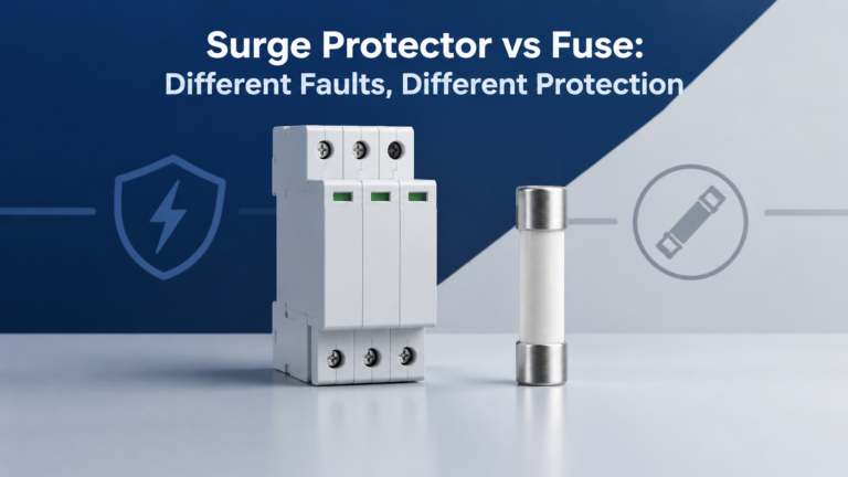
A surge protector limits transient overvoltage; a fuse interrupts overcurrent. Learn the differences, combined-device limits and checks for coordinated protection.