A Type 2 DC surge protection device (SPD) is wired in parallel between the DC conductors and earth: its positive terminal connects to DC+, its negative terminal to DC−, and its earth terminal to the protective earthing busbar. Get that connection wrong, or install the SPD in series with the load, and the device cannot do its job — and in some cases it can damage itself or the equipment it is meant to protect. This guide shows the standard Type 2 DC SPD wiring arrangement for photovoltaic (PV) and other DC systems, walks through installation step by step, and lists the wiring mistakes that cause most field failures.
The scope here is the SPD itself: how its terminals are connected, where it sits in the circuit, and how it is mounted and verified. For the wider picture of how an SPD shares a solar combiner box with string fuses, a DC MCB and the inverter feed, see the site guide to solar combiner box wiring diagrams. For help choosing the Type 2 DC SPD model in the first place, the Type 2 DC surge suppressor selection guide covers ratings and application.
Type 2 DC SPD Wiring at a Glance
A Type 2 DC SPD behaves like a voltage-controlled switch connected between each DC conductor and earth. Under normal operation it is effectively invisible: almost no current flows through it. When a lightning-induced or switching surge raises the voltage above its clamping level, the SPD becomes conductive, diverts the surge current to earth, and clamps the voltage that the protected equipment sees. When the surge passes, it returns to its high-impedance state. This is why the SPD must be connected in parallel with the protected circuit — never in series.
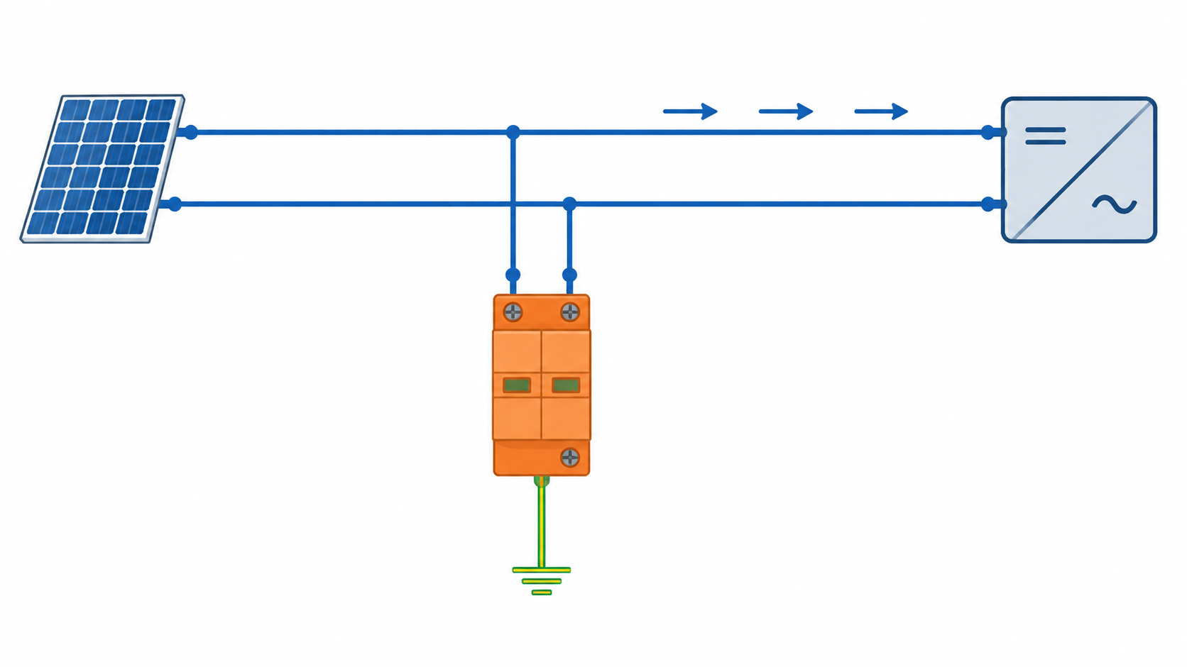
A typical three-terminal Type 2 DC SPD for a two-wire PV circuit is wired as follows:
SPD terminal
Connect to
Purpose
+ (DC+)
Positive DC conductor from the array or battery
Voltage limiting between DC+ and earth
− (DC−)
Negative DC conductor
Voltage limiting between DC− and earth
⏚ / PE
Protective earth (PE) busbar or grounding point
Surge current path to earth; must be short and low impedance
Terminal markings and the number of protected poles vary by manufacturer and by SPD configuration. Always follow the wiring diagram printed on the specific device and its data sheet.
Conceptual wiring diagram only, not a site drawing or to scale. The SPD is tapped in parallel; load current continues past it to the inverter.
Where a Type 2 DC SPD Belongs in a PV System
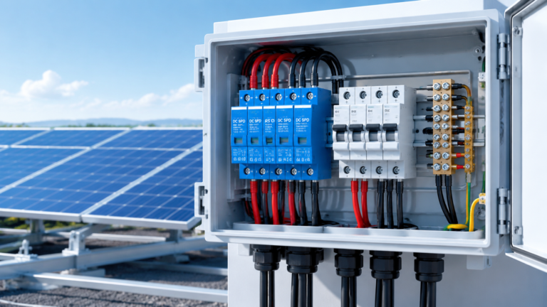
Type 2 DC SPDs are installed on the DC side of photovoltaic systems, typically at one of two locations: inside a solar combiner box at the array, or at the DC input of the inverter. In larger systems the SPD may be fitted at both points, with the more exposed location carrying the heavier surge duty.
The physical rule is simple: the SPD should sit as close as practical to the equipment it protects, and its connecting leads must be as short as possible. Long leads add inductance, and inductance raises the effective protection level — a device with an excellent voltage protection rating (Up) can still let a damaging voltage through if it is wired with metre-long tails. Most installation instructions ask for each SPD lead to be kept under roughly 0.5 m; where the SPD and the protected equipment are far apart, a second SPD closer to the equipment is normally the better answer than a single device with long leads.
Because the DC side of a PV system behaves differently from an AC mains circuit, the SPD must be a DC-rated model with a DC voltage rating matched to the array. The difference between AC and DC surge protection is not cosmetic — voltage, discharge capability and fault behaviour all differ. See the comparison of AC SPD vs DC SPD before selecting a device for a solar application.
Before Wiring: Confirm the SPD Matches the System
No wiring diagram can compensate for an SPD that does not match the circuit. Check these values against the SPD data sheet before mounting anything:
Maximum continuous operating voltage (Ucpv for PV SPDs). The SPD rating must be above the highest continuous voltage the DC circuit can present. For a PV array this is related to the string open-circuit voltage at the coldest expected temperature. A DC SPD selected with a Ucpv below the system voltage will be stressed continuously and can fail early.
Nominal discharge current (In) and maximum discharge current (Imax). These describe the surge the SPD can handle in the 8/20 µs test wave. Choose the class according to surge exposure at the site; Type 2 devices are the common choice for protecting inverter inputs and combiner boxes against induced surges.
Voltage protection level (Up). The clamped voltage the SPD lets through must be lower than the impulse withstand of the protected equipment. If Up is above the equipment rating, the SPD will clamp too late to protect it.
Polarity. Many DC SPDs are polarity-sensitive. Confirm the + and − markings match the circuit before connecting; a reversed DC SPD can conduct continuously and overheat.
Short-circuit withstand and backup protection rating. The data sheet states the maximum backup fuse or circuit breaker that may be installed upstream, and the fault current the SPD can withstand. Use that value, not a guess.
Tools and Materials for a Type 2 DC SPD Installation
A DIN-rail Type 2 DC SPD installation is a small, tidy job when the materials are ready:
Type 2 DC SPD rated for the system voltage (Ucpv) and surge class
DC-rated cables sized for the circuit, with insulation rated for DC voltage
Protective earth (PE) conductor, green/yellow where colour coding is required
DC backup protection: a gPV fuse or DC-rated MCB matching the SPD data sheet
DIN rail (if not already fitted) and the enclosure or combiner box
Cable lugs, ferrules and a torque screwdriver appropriate for the terminal size
Label material for marking the SPD circuit
Working on a live DC circuit is dangerous: PV strings are energised whenever light hits the panels and cannot be simply switched off at a load. Plan the work so the relevant strings are isolated, covered, or otherwise made safe before terminals are opened.
How to Wire and Install a Type 2 DC SPD: Step by Step
Step 1 — Isolate and Verify the Circuit Is De-energised
Open the DC isolator or disconnect the relevant strings and confirm the DC conductors are at zero voltage before opening the enclosure. On PV installations, cover the modules or otherwise remove the light source if disconnecting a live string is unavoidable.
Step 2 — Mount the SPD on the DIN Rail
Clip the SPD onto the DIN rail inside the enclosure, close to the busbar or terminal block it will protect. Position it so the leads to DC+, DC− and earth can run as short and straight as possible. Make sure the module is fully engaged on the rail and does not rock when pressed.
Step 3 — Connect the Backup Protection (DC Fuse or MCB)
If the SPD data sheet requires backup protection — and most DC SPDs do — install the specified gPV fuse or DC MCB on the supply side of the SPD tap. The backup device isolates the SPD if it fails to a short-circuit condition and protects the branch during a fault. Selecting the backup rating is covered in the guide to SPD yedek sigortası veya devre kesici seçimi.
Step 4 — Wire the SPD Terminals in Parallel
Connect each SPD terminal to the corresponding point on the DC circuit:
SPD + terminal to the positive DC conductor (after the backup protection)
SPD − terminal to the negative DC conductor
SPD earth terminal to the PE busbar
Check polarity against the device markings, tighten each terminal to the torque stated on the SPD or data sheet, and keep the conductors as short and direct as the layout allows. Do not coil spare cable length near the SPD: loops add inductance to the surge path.
Step 5 — Verify the Earth Connection
The earth connection is part of the surge current path, so it must be as short and low-impedance as the DC connections. Connect the SPD earth terminal to the protective earth busbar of the same enclosure or system, and confirm that the earthing system itself is sound. A floating or high-resistance earth leaves the surge nowhere to go and defeats the SPD.
Step 6 — Label, Close and Record
Mark the SPD and its backup protection on the enclosure schedule so a future maintenance engineer can identify the circuit. Note the installation date and the SPD model in the maintenance log, because DC SPDs age with every surge they absorb and need periodic checks.
The Most Common Wiring Mistake: Series Instead of Parallel
The single most common field error is installing the SPD in series with the protected load — that is, cutting the DC conductor and passing all the load current through the SPD. A Type 2 DC SPD is not designed for this. In series it becomes a permanent obstruction in the power path and can overheat or fail in normal operation, and it still provides no useful clamping because the surge sees the wrong circuit topology.
The correct arrangement is always parallel: the SPD is tapped across the DC+ and DC− conductors (and to earth) while the load current continues to flow past it, through the circuit’s own protection and switching devices. If a wiring diagram shows the SPD in the main power path, treat the drawing as wrong.
Other DC SPD Wiring Mistakes to Avoid
Leaving long connecting leads. Lead inductance raises the effective protection level. Keep each lead short — typically well under 1 m and preferably around 0.5 m or less — and never extend an SPD with long tails to reach a distant busbar.
Connecting an AC SPD to a DC circuit. AC and DC SPDs are rated differently and a DC fault does not self-extinguish like an AC zero-crossing fault. Use a DC-rated SPD such as a Type 2 DC model tested to the PV SPD standard.
Reversing polarity on a polarised DC SPD. A reversed MOV-based DC SPD can conduct continuously and overheat. Verify + and − before energising.
Omitting the required backup protection. If the data sheet calls for a backup fuse or MCB, fit it. Without it, a failed SPD that shorts can go unnoticed until the fault escalates.
Sharing the SPD earth with a noisy or high-resistance path. The SPD earth must be the protective earthing system, connected solidly to the PE busbar.
Installing the SPD far from the equipment it protects. Distance reduces protection. When the protected equipment is remote, install a second SPD near it rather than relying on one distant device.
Checking a Type 2 DC SPD Installation Before Energising
Before closing the enclosure and restoring power, run through a short verification list:
Confirm the SPD model and Ucpv match the system voltage, and the surge class matches the exposure.
Confirm polarity: SPD + on DC+, SPD − on DC−.
Confirm the SPD is in parallel with the circuit, not in the power path.
Confirm the backup fuse or MCB rating matches the SPD data sheet and is installed on the supply side.
Confirm every terminal is tightened to the specified torque.
Confirm the earth conductor is continuous, short and connected to the PE busbar.
Check the SPD status window (where fitted) shows the normal indication before energising.
After installation, the SPD should be inspected periodically rather than installed and forgotten. How to check a device that may have absorbed surges — including the red/green status window and when to replace the module — is covered in the guides to the SPD failure indicator and to backup protection on this site.
Type 2 DC SPD Wiring Diagram: Common Questions
Does a Type 2 DC SPD go in series or in parallel?
Always in parallel with the DC circuit it protects. The SPD is connected between DC+, DC− and earth while the load current flows through the circuit’s own conductors and protection devices. Connecting an SPD in series is a wiring error.
Which wires go to the SPD terminals on a PV system?
On a standard two-wire DC SPD: the + terminal to the positive DC conductor, the − terminal to the negative DC conductor, and the earth terminal to the protective earth busbar. Follow the terminal diagram printed on the device, since configurations with different numbers of poles exist.
Can I install a Type 2 DC SPD without a backup fuse or breaker?
Only if the SPD data sheet explicitly states it needs none, usually because the device has a tested internal disconnector and is certified for that arrangement. Most DC SPDs list a maximum backup gPV fuse or DC MCB rating, and the manufacturer’s instructions should be followed.
How close should a Type 2 DC SPD be to the inverter?
As close as the layout allows. Long leads add inductance and raise the voltage the equipment actually sees. Where the SPD must be remote from the protected equipment, add a second SPD at the equipment rather than lengthening the first device’s leads.
What happens if a DC SPD is wired with reversed polarity?
A polarised DC SPD connected the wrong way can conduct continuously instead of only during a surge, which leads to overheating and early failure. Always verify the + and − markings before energising the circuit.
Wire the SPD Correctly and It Stays Out of the Way Until a Surge Arrives
A correctly wired Type 2 DC SPD is a low-maintenance insurance policy: parallel connection, short leads, solid earthing, matched ratings and the specified backup protection. The diagram on the device data sheet is authoritative; this guide explains the logic behind it so that a review of any proposed wiring can be done with confidence.
Çoğu güneş enerjisi DC dağıtım kutusu (DCDB), 8/20 µs dalgalanma akımlarına uygun Tip 2 DC dalgalanma koruma cihazı (SPD) ile donatılmıştır; DC devresinin doğrudan yıldırım çarpmasına maruz kalması veya tesisin harici bir yıldırım koruma sistemine sahip olmaması durumunda Tip 1+2 DC SPD gereklidir. Bu kılavuzda, nasıl karar verileceği açıklanmaktadır […]
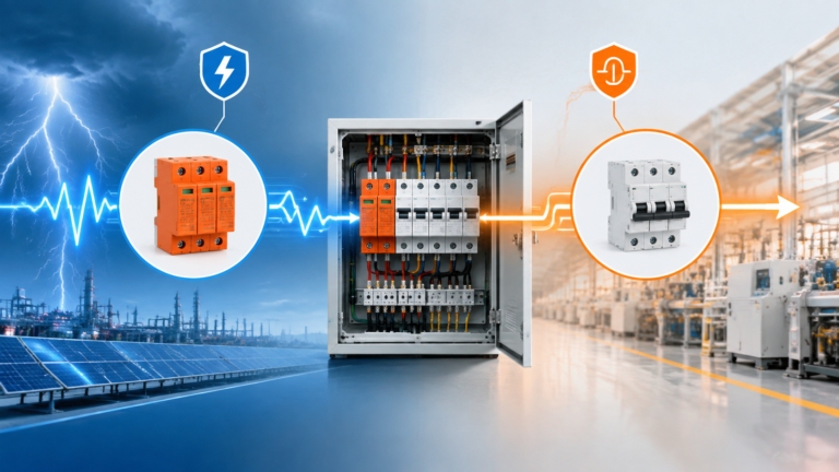
Aşırı gerilim tutucular geçici aşırı gerilimleri sınırlar; devre kesiciler ise aşırı yükleri ve kısa devreleri ortadan kaldırır. İşlevlerini, uygulama alanlarını ve koordinasyonlarını karşılaştırın.
Aşırı gerilim koruyucu, geçici aşırı gerilimi sınırlar; sigorta ise aşırı akımı keser. Aralarındaki farkları, birleşik cihazların sınır değerlerini ve koordineli koruma için yapılması gereken kontrolleri öğrenin.