




Bir DC Aşırı Gerilim Koruma Devresinin Çalışma Prensibi
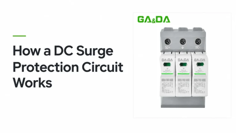
Follow a DC surge protection circuit through normal operation, a surge and recovery, and see why protection modes and DC fault disconnection need their own design.
Daha Fazlasını Oku Turkish

Selecting the wrong surge protective device type is one of the more common and more expensive specification errors in low-voltage installations. The device may work, the installation may pass inspection, and the system will still be under-protected for the actual risk it faces — because Type 1, Type 2, and Type 3 devices are not ranked versions of the same thing. They answer different questions.
This guide sets out how to choose between the three types. It works as a decision tree: start from the installation’s lightning protection zone and the origin of the threat, arrive at the device type, then confirm the parameters that must match. Detailed comparison of Type 1 and Type 2 characteristics is covered separately, as is the parameter-by-parameter sizing of Type 2 devices for low-voltage distribution.
The three types are distinguished by the test waveform they are certified against, and that test defines what they can do.
Type 1 (Iimp) is tested with a current impulse representing a partial direct lightning current — the kind that flows when a building’s air termination or external conductors are struck. It is defined by Iimp, in kA, representing the partial current the device can withstand at 100 ms.
Type 2 is tested with a current or voltage impulse representing induced effects: nearby lightning discharges, switching transients in the power system, and coupling from neighbouring installations. It is defined by a combination of Imax, In, Isc, and Up depending on the device topology.
Type 3 is tested with a combined waveform representing induced effects at a lower energy level, intended for protection of specific downstream equipment rather than whole installations. It is defined by Uoc, the open-circuit voltage of the test.
The practical consequence: a Type 2 device cannot substitute for a Type 1 where a direct strike is possible, because it has never been tested for that current profile. Equally, installing Type 1 everywhere is not automatically better — the test category exists to match the device to the actual threat.
Three questions determine the device type, in order:
If the first question cannot be answered, the protection cannot be specified correctly. This is the step most often skipped.
When lightning can strike the structure itself, or external conductors such as a mast or air termination, the surge that reaches the installation is a partial lightning current. This is the Type 1 case. It is the only category tested for this profile.
The far more common case. The lightning channel does not touch the building; it induces a transient on nearby conductors, which couples into the installation through mains wiring, external cables, or long internal runs. Type 2 addresses this.
Energising loads, capacitor bank switching, transformer inrush, and the operation of devices upstream all generate transient overvoltage on the distribution network. These are entirely unrelated to lightning and are handled by Type 2 devices.
Where a device sits at the end of a long external or internal cable run, induced effects arrive attenuated in energy but still capable of damaging sensitive equipment. A Type 3 device, installed close to that equipment, addresses this specific case.
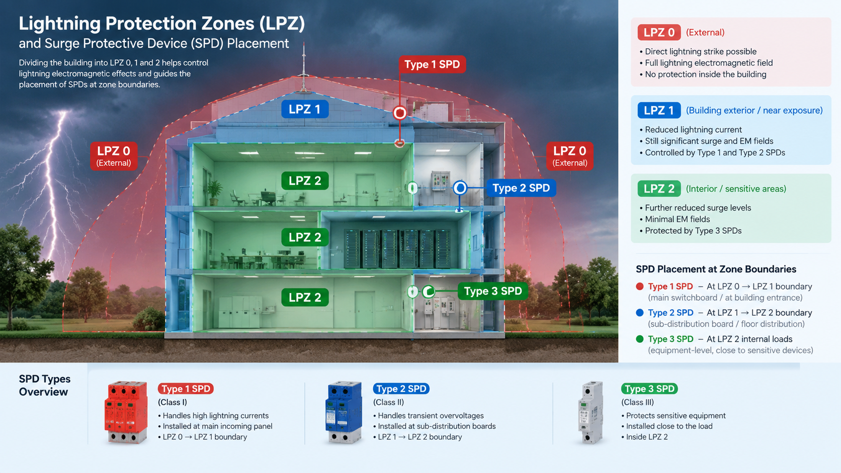
Per IEC 61643-11, a building’s lightning protection system divides it into lightning protection zones. The zone structure follows from the presence of external LPS elements and the building’s construction.
The SPD requirement per zone follows a recognised pattern: Type 1 devices at the boundary from LPZ 0 to LPZ 1, Type 2 devices at the boundary from LPZ 1 to LPZ 2, and Type 3 devices at the protected equipment where distance from the LPZ 2 boundary exceeds 10 metres of cable or 20 metres of conduit routing.
That last distance criterion is where Type 3 earns its place. A Type 2 device at the main distribution board does not protect equipment 25 metres of cable downstream from induced effects arriving on that cable — the transient is generated along the run itself.
| Situation | Required type | Basis |
|---|---|---|
| Building with external LPS (mast or air termination) | Type 1 + Type 2 | Direct currents at LPZ 0/1, induced effects at LPZ 1/2 |
| Building without external LPS, overhead line arrival | Type 2 | No direct current path; induced effects only |
| Underground supply, no overhead lines | Type 2 | Induced effects and switching transients |
| PV DC side, cable over 10 m before inverter | Type 2 PV-rated | Induced effects along the DC run |
| Equipment more than 10 m cable from SPD at LPZ 2 | Add Type 3 at equipment | Induced effects on the downstream run |
| Building in a high lightning-risk region with no LPS | Type 2, recommend LPS | Protection cannot exceed source capability |
Two rows deserve emphasis. The last is the honest answer for a site with no lightning protection system and frequent strikes: no SPD compensates for the absence of an LPS, and specifying higher-category devices is not a substitute for air termination and down-conductors.
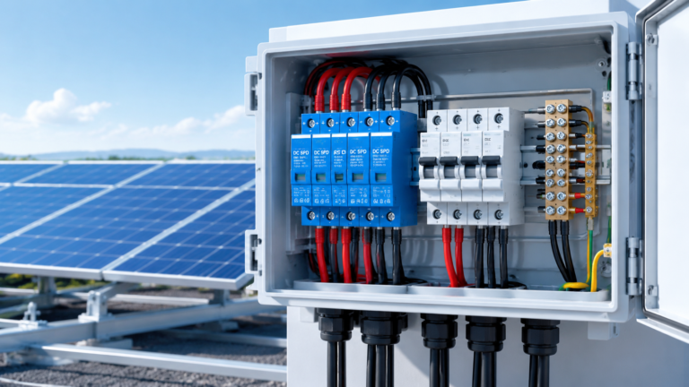
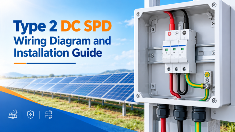
The fourth row applies to nearly every photovoltaic installation. PV DC cables run outdoors for substantial distances, which places them squarely in the induced-effects case and makes Type 2 PV-rated devices standard on the DC side.
Type 1 devices sit at the LPZ 0/1 boundary, which in practice means the incoming mains entry point, close to the building’s main switchboard and before any significant cable run. They are normally installed alongside Type 2 devices rather than instead of them.
Critical specification points: Iimp must be selected against the likely partial current, typically 25 kA for residential and small commercial buildings in high-risk regions, higher where the LPS is minimal relative to the building size. The device must be capable of withstanding the current long enough for the LPS down-conductors to take the majority of the energy to earth.
GA&DA supplies Type 1 SPDs in the GA&DA GD-series range, including the G2035MT and G2050MT configurations for distribution applications.
Type 2 is the default device type for low-voltage installations, and most projects need nothing else. It is installed at the LPZ 1/2 boundary — typically the main distribution board — and covers both induced lightning effects and switching transients across the whole installation.
Specification depends on topology:
Key parameters: Yukarı (maximum protection voltage) must sit below the withstand voltage of downstream equipment; Uc must equal or exceed the nominal system voltage; İçinde veya Imax must be coordinated with the backup protection. Detailed sizing guidance for these parameters is covered in the dedicated Type 2 selection article.
GA&DA’s Type 2 range spans the GA&DA GD-MT, GD-DZ, and GD-XZ series across pole counts and current ratings, with DC and PV variants available for photovoltaic applications.
Type 3 is the least understood and most frequently misused of the three. It is not a weaker Type 2; it is a different test profile for a specific position in the installation.
Its purpose is protecting specific equipment against induced effects arriving along a long cable run. The measured parameter is Uoc, the voltage the device produces when disconnected. Uoc must be compared against the equipment’s withstand voltage — a Type 3 device with a Uoc above the equipment’s rating provides no protection regardless of how well it is installed.
Typical Type 3 positions: at the inlet of sensitive equipment, at the final sub-distribution board serving an IT or process load, or on individual circuits leaving the main board for long runs.
Two practical notes. First, Type 3 devices must not be installed as the sole protection for a distribution board. Second, because Uoc is the reference parameter, specifying Type 3 by a current rating such as “20 A” is meaningless — the comparison that matters is Uoc against equipment withstand voltage.
Once the type is chosen, four parameters must be confirmed against the installation:
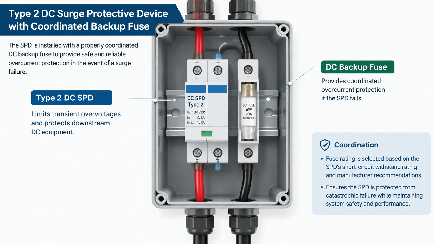
Backup protection coordination deserves particular attention. A Type 2 device that fails short-circuit at end of life must be cleared by its backup device. This requires the available fault current at the installation point to fall within the device’s specified Imax/Isc range and the backup fuse to be correctly rated. Specifying Imax below the actual prospective fault current removes the manufacturer’s coordination guarantee.
In practice, most installations need more than one type:
GA&DA manufactures Type 1, Type 2, and Type 3 surge protective devices across AC and DC applications, including PV-specific models for photovoltaic systems and signal and network protection variants. See the full aşırı gerilim koruma cihazları range, or review related technical guidance on surge current capacity and response time and DC circuit behaviour.