Solar Combiner Box Problems: Faults, Tests and Fixes
Publicado: Autor: Rachel
Solar combiner box troubleshooting begins with one rule that overrides everything else: a blown string fuse or a tripped DC breaker is a symptom, not a fault. Something drew more current than the circuit was designed for, or the protective device was the wrong choice for the job. Replacing the fuse or resetting the breaker without establishing which of those two it is, is how a small defect becomes a burnt busbar or a sustained DC arc on a 1500 V string.
This guide is written for the person standing in front of an open enclosure on a rooftop or in a solar farm. It follows a fixed order — symptom, safe isolation, measurement, root cause, fix, prevention — and treats every fault as something to be proved by measurement rather than guessed at. For the internal layout, our Esquema de cableado de la caja de conexión solar shows where each string fuse, breaker and SPD sits in the circuit; this article deals with what happens when the box misbehaves.
Why a Fuse or Breaker Operating Is Never the Diagnosis
A protective device has one job: interrupt before the cable or the equipment is damaged. When it operates it is reporting a condition — overload, short circuit, reverse current, transient — that crossed its threshold. Three different stories produce identical evidence:
A real fault cleared correctly. A damaged module, a pinched string cable, a flooded connector or a shorted diode pushed current above the fuse rating. The fuse did its job. The fault is still there.
Nuisance operation from a selection or environment problem. The rating never matched the string’s real conditions — high internal temperature, thermal cycling, the wrong fuse class, or a holder that does not make reliable contact. The device worked; the design is wrong. The gPV fuse selection guide for 1000 V and 1500 V strings covers how the rating should have been chosen.
A degraded device. A holder that has been hot for years, a breaker tripped repeatedly, or a corroded terminal can cause operation with no fault in the array at all.
Re-energising repeatedly to “see if it holds” destroys the evidence and, because a DC circuit has no natural current zero, risks an arc that will not extinguish. Diagnose first, energise once.
Safety-First Field Procedure
Every step below assumes this has already been done. It is not abbreviated for a “quick look”.
Plan and permit. Know the string-to-terminal schedule before opening anything. A combiner box can be fed from the array side and, on a battery or hybrid system, from the inverter side too — treat it as dual supply and label it.
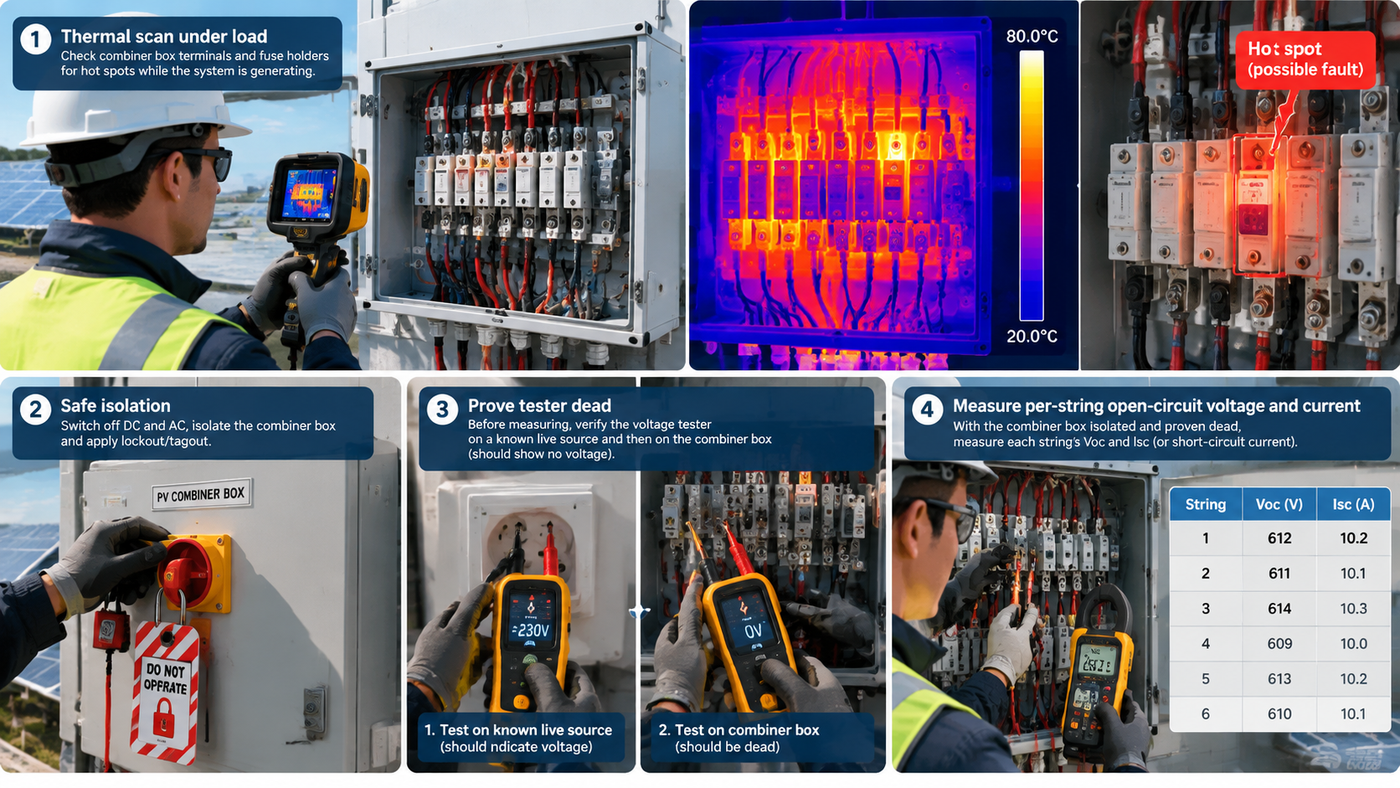
Do load-dependent checks first. A thermal scan only means something while the array is producing. Scan under realistic irradiance before isolating, because hot joints cool the moment current stops.
Record the as-found state. Photograph the interior, note indicators, string currents, ambient temperature and time of day. You cannot reconstruct this later.
Isolate. Open the DC isolator or switch-disconnector and, where provided, the string fuses. On a battery-connected system, isolate the battery side too.
Verify dead and prove the tester. Prove the tester on a known live source, prove the conductors dead at the point of work, then prove the tester again. Test pole-to-pole and each polarity to earth. PV conductors stay live in daylight even with the isolator open — the modules are the source.
Protect yourself. Arc-rated clothing, insulated gloves and a face shield for anything involving energised DC terminals. Insulated tools, one hand where practical.
Never work on energised PV strings. Insulation-resistance and continuity tests require the string isolated from both the combiner and the inverter.
Restore in a controlled order, only after the root cause is corrected, watching the first minutes of load.
The Troubleshooting Sequence
Work the same six steps whatever the symptom. Skipping to the fix is why the same fault returns within a month.
Symptom. Exactly what is observed — failed fuse, tripped breaker, red SPD window, low string current, comms alarm? Record it with time and weather.
Isolation. Make the box safe, then separate the affected string from the healthy ones so you can measure it alone.
Measurement. Take the measurements listed for that symptom and compare against the approved design values, not a remembered number.
Root cause. Identify the physical reason the measurement is out — not the component that failed.
Fix. Repair the cause, then replace the affected device with the correct type and rating from its datasheet, in a matching holder. The fuse size chart for 10×38, 14×51, 22×58 and 14×85 is the reference for physical size and holder matching.
Prevention. Decide what changes to design, maintenance interval or practice stop the same fault recurring, and record it.
Master Fault Table
Use this as a starting point. Every entry still has to be confirmed by measurement on the box in front of you.
Fault observed
Likely cause
How to confirm
Action
String fuse blown, one string only
Reverse or back-feed current from parallel strings into a fault in that string; module or connector failure; shorted bypass diode
Isolate and measure string open-circuit voltage; measure insulation resistance to earth; clamp the remaining strings for an abnormal rise
Repair the string fault first, then fit an identical type and rating. Never fit a larger fuse
String fuse blown, several strings
Common-mode event — surge, earth fault on the busbar, or an SPD that failed without clearing
Check SPD indicators and backup protection; inspect busbar and enclosure for arc marks; measure insulation resistance per string
Treat as a system event, not a string event. Inspect the whole box before re-energising any string
DC breaker tripped, trips again on reset
Genuine overcurrent or short in the protected circuit
Measure insulation resistance and load current with the breaker in a safe test configuration; look for a downstream short
Find and clear the fault. Do not raise the rating and do not keep resetting
DC breaker tripped after a surge or storm
Transient overvoltage, lightning-induced surge, or real damage from wind or water entry
Inspect connectors, cable routes and glands; check SPD state; measure string insulation resistance
Repair damage, replace consumed SPD modules, then restore once
SPD status window red / showing end of life
Thermal disconnection after cumulative surge exposure, sustained overvoltage, or moisture ingress
Read the indicator per the device instructions; check the backup protection and the earthing conductor
Failed door gasket, unsealed spare entry, top-mounted gland, or condensation without ventilation
Inspect gasket and glands; look for water tracking and mineral residue; check whether desiccant or breather is saturated
Reseal and re-gland from below where possible, replace gasket and desiccant, then retest insulation resistance
White or green corrosion on terminals and busbars
Long-term moisture plus dissimilar-metal contact; damaged plating; coastal salt
Visual and tactile inspection with the box isolated; measure contact resistance or voltage drop across the joint
Replace corroded busbar and terminals rather than cleaning in place. Recheck IP integrity and material compatibility
Hot terminal or discoloured busbar on thermal scan
Loose connection, insufficient torque, corroded contact surface, or undersized conductor
Scan under load with a known current, then verify torque against the manufacturer’s value after isolation
Remake the joint to clean metal, torque to the datasheet value, re-scan under load
Reverse current in a string
Short circuit within a module string, a mis-wired string, or unequal string voltages in parallel
Compare per-string current direction with a clamp meter; compare open-circuit voltages measured at the same moment
Disconnect and repair the affected string; confirm fuse and cable are rated for the reverse-current path
Earth fault alarm or low insulation resistance
Damaged cable insulation, water in a connector or junction, faulty module, genuine earth contact
Insulation-resistance test per string at the appropriate test voltage, strings isolated and dry; sectionalise to locate
Repair or replace the damaged section. Never disconnect earthing to silence an alarm
One string well below the others
Shading, soiling, failed module or diode, loose connector, partially open fuse holder, mis-specified string
Measure per-string operating current at the same moment and irradiance; measure Voc; compare with neighbours
Correct the physical cause, then re-verify under matched conditions
Monitoring or communication fault, no data
Unpowered or failed monitoring module, loose signal wiring, wrong address or baud setting, water in a connector
Check supply at the module, verify wiring continuity, compare configuration against the commissioning record
Restore supply and wiring, re-apply the documented configuration, confirm data at the head end
Blown String Fuses
In a combiner box the string fuse mainly protects against reverse current. When one string develops a short, the parallel strings feed current into it — potentially far above the module’s reverse-current capability — and the fuse limits it. That is why a blown string fuse usually points at the string it protects, not at the box.
Isolate the string and measure open-circuit voltage. Near-zero or well below the temperature-corrected design value indicates a short or open inside the string.
Measure insulation resistance from each polarity to earth. A low reading points to cable or connector damage, or water entry.
Clamp the parallel strings with the affected one isolated. Normal currents elsewhere mean the fault is contained; several low strings mean a common cause.
Inspect the holder as carefully as the fuse. Heat marks, discolouration or a sprung contact mean the holder must be replaced, or it will blow the next fuse.
The replacement must match type, current rating, voltage rating and physical size. A gPV fuse and a general-purpose fuse of the same current rating are not interchangeable on a DC string. If the original rating looks wrong for the string, work it out using the gPV guidance above rather than guessing, and keep replacements within one fuse product range so holder and device stay compatible.
Tripped DC Breakers
A DC breaker trips for overload, short circuit or an earth fault inside its protected zone. Because it can be reset, it gets abused: resetting into a persistent fault arcs at the contacts and progressively damages the mechanism.
Trip once, investigate, then trip no more. Immediate re-trip means something is still shorted or overloaded.
Check the breaker’s own condition. A device that has interrupted a large fault, or been operated many times under load, may have degraded contacts. Assess it against the manufacturer’s guidance before returning it to service.
Use the trip record. An indicator or an auxiliary contact wired to monitoring separates an overcurrent trip from an earth-fault or shunt trip and narrows the diagnosis considerably.
Never uprate or re-set to stop nuisance tripping. If it trips in normal operation, the coordination between string current and the device datasheet needs review. Selectivity matters too: if a string fault trips the main DC breaker instead of the string fuse, one string problem takes the whole array offline — a design issue worth reviewing.
SPD at End of Life
A surge protective device is a consumable. It absorbs energy until it can absorb no more, then disconnects itself to avoid overheating. The useful question is not “the SPD failed” but “what did it absorb, and was the installation able to deliver that energy to it properly?” Clicking in a new cartridge and closing the door is how you get a repeat failure.
Two things to check every time. First the protección mediante copias de seguridad: an SPD needs an upstream fuse or breaker coordinated with it, and if that device is the wrong type or rating the SPD may not clear safely. Second the earthing and connecting leads: long, thin or poorly bonded connections raise the residual voltage at the equipment terminals and shorten device life. Reading the status window is covered separately in our post on the Indicador de fallo del SPD. Never leave a spent SPD position empty and never bridge it — an unprotected combiner box on a 1500 V DC system is a worse outcome than a device that needs replacing.
Water Ingress, Condensation and Corrosion
Water is the most common long-term killer of combiner boxes, and it arrives two ways that need different fixes.
Ingress — water entering from outside: failed door gaskets, spare entries left open, glands fitted on the top face, damaged seams. The fix is mechanical: reseal, re-gland, re-orient.
Condensation — water forming from the air already inside. Daily temperature cycling deposits moisture on cool internal surfaces. The fix is a breather or pressure-compensation element, a desiccant where the design uses one, and reduced solar gain. A perfectly sealed box in a humid climate can still fill with condensate.
Corrosion follows. Once moisture is present, dissimilar-metal joints, damaged plating and coastal salt accelerate it; higher contact resistance raises temperature under load, which accelerates corrosion further. When corrosion has reached the busbar, replace it — cleaning in place restores appearance, not cross-section. After any wet event, repeat the insulation-resistance test before returning the box to service.
Loose Terminals, Hot Joints and Discoloured Busbars
Thermal faults are the most preventable in this article and the ones usually discovered too late. The sequence is predictable: a joint not torqued to the manufacturer’s value develops slight resistance, resistance produces heat, heat relaxes the joint, resistance rises further. By the time a busbar is visibly discoloured, the joint has been hot for a long time.
Scan under load. Thermography on an unloaded box shows nothing. Record the load or irradiance with the image, and compare the suspect joint against a similar joint in the same box rather than an absolute temperature.
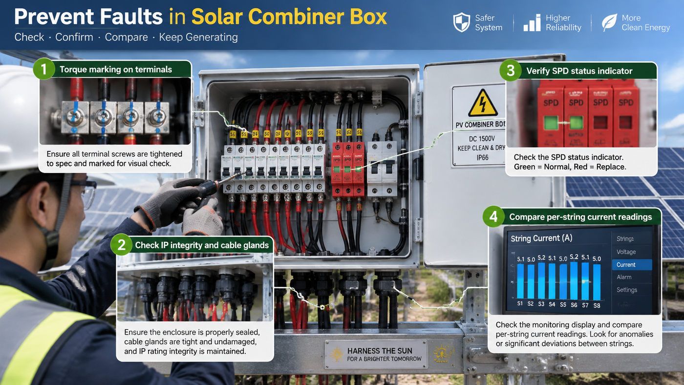
Torque to the datasheet, not to memory. Every terminal has a value set by its manufacturer — fuse holders, breaker terminals, busbar lugs and SPD connections all differ. Use a calibrated torque wrench and the published figure, then mark the joint so the next person can see it has been visited.
Look at the conductor. Discoloured insulation near a lug, or a stranded conductor that has lost its shape, indicates sustained overheating: remake the termination rather than retightening it.
Check holder contacts. Poor contact pressure heats the fuse caps. Any sign of arcing or discolouration means replace the holder.
Reverse Current Between Parallel Strings
Parallel strings in one box must operate at essentially the same voltage. If one string sits lower — a shorted module, a shorted bypass diode, a damaged connector, a mis-wired string — the healthy strings push current into it. That reverse current is what the string fuse interrupts, and it is why an un-fused parallel string is poor design. Confirm it with the box isolated: compare per-string open-circuit voltages measured back-to-back under the same conditions, then compare operating currents with a clamp meter. A string sitting noticeably below its neighbours has a fault inside it; take it out of service and repair it before restoring the box.
Earth Faults and Insulation Resistance
An earth fault is any unintended path from a live conductor to earth. Detection differs by design — continuous insulation monitoring, residual-current monitoring, or periodic testing — but the diagnostic approach is the same: sectionalise.
Isolate the strings from the combiner and the combiner from the inverter.
Test each string separately, positive to earth and negative to earth, at the test voltage appropriate to the system. IEC 62446-1 is the reference commonly used for PV commissioning tests — read the current edition and the project specification for acceptance criteria rather than relying on a remembered value.
Test on dry modules. Dew or recent rain depresses a healthy reading and will send you hunting for a fault that is not there.
Split a failing string at junction boxes and connectors until the damaged section is found.
Never disconnect or remove protective earthing to clear an alarm. That converts a monitored fault into an unmonitored shock and fire risk.
One Underperforming String
A single low string is the most common complaint on an operating array, and it has both fault and non-fault causes. Separate them before condemning anything.
Non-fault causes: shading from a new structure, mast or growing tree; soiling concentrated at one end; a changed tilt or azimuth after a repair; snow or debris on part of the array. No repair will fix these.
Fault causes: a failed module or bypass diode, a loose or water-filled connector, a partially open fuse holder, a high-resistance joint, or a broken conductor showing as an early-morning and evening-only difference.
Measure per-string operating current at the same moment on the same array — sequential readings across an hour of changing irradiance are not comparable. Then measure Voc per string. Normal Voc with low operating current suggests series resistance; low Voc suggests a missing or shorted section.
Monitoring and Communication Faults
A monitoring fault is rarely an array fault, but it can hide one. Treat a data loss as two questions: is the array still producing, and is the reporting path broken?
Confirm production independently — inverter display or a clamp meter — before assuming a generation loss.
Check supply to the monitoring module, then wiring continuity, then configuration against the commissioning record: addresses, baud rate, protocol and channel-to-string mapping.
Inspect the signal connector for water or corrosion. A monitoring fault that appears after rain is an ingress fault.
Treat a single channel reading zero with suspicion — a failed sensor and a failed string need very different responses.
What to Measure, and With What
Measurement
Objetivo
Condition required
Thermal image of terminals, busbars and fuse holders
Find high-resistance joints before they fail
Under realistic load, before isolation
Per-string operating current (clamp meter)
Identify the underperforming or reverse-current string
All strings connected, same moment, irradiance recorded
Per-string open-circuit voltage
Detect a shorted or open section inside a string
String isolated at the combiner; compare with the temperature-corrected design value
Insulation resistance, each polarity to earth
Locate earth faults and damaged insulation
Strings isolated from combiner and inverter, dry modules
Two habits make the results useful. Record the conditions — time, irradiance, ambient and internal temperature — because a PV measurement without conditions is comparable to nothing. And compare like with like: within the same box, at the same moment, against the approved design values.
Preventing the Next Fault
Verify the design values at commissioning — per-string current, Voc, insulation resistance and thermography, all recorded, so later measurements have a baseline.
Do the load-dependent checks first at every visit, because thermal faults are only visible while current flows.
Re-check torque on a schedule and mark joints, so a loose terminal is found before it discolours a busbar.
Protect the IP rating continuously — every spare entry blanked, every gland correctly sized and fitted, gaskets replaced when they harden.
Treat every operated protective device as an investigation trigger, and keep spares of the correct type and rating on site so a replacement is never a compromise.
If you are diagnosing a fault on a box we supplied, or you need replacement fuses, holders or SPD modules matched to an existing installation, our technical team can work from photographs of the nameplate and the as-found condition — start at the contact page and include the string schedule. For the basics of what the box contains and why, see what is a solar combiner box.
Preguntas frecuentes
Why does my solar combiner box fuse keep blowing?
Because the cause of the first failure was never found. In a combiner box a string fuse normally operates on reverse current from the parallel strings, which means the fault is inside the string it protects — a shorted module, a damaged connector, or water in a junction. Replace the fuse only after the string’s open-circuit voltage and insulation resistance have been measured and the fault repaired. A heat-damaged holder will also blow the next fuse, so inspect the holder too.
Can I just reset a tripped DC breaker in a combiner box?
Reset it once while watching the current, but if it trips again the diagnosis comes first. Repeated resetting into a persistent fault arcs at the contacts and damages the breaker. Do not increase the rating or change the setting to stop the tripping — if it operates under normal operating current, the coordination between the breaker, the string current and the datasheet needs reviewing.
How do I tell whether a combiner box problem is the fuse or a real fault?
By measuring, not by replacing. A real fault leaves evidence: abnormal string open-circuit voltage, a low insulation-resistance reading, a thermal hotspot, water or corrosion, or abnormal current in the parallel strings. If all of those measurements are normal and the fuse still operates, suspect the device selection or the holder contact instead.
Is it safe to open a solar combiner box during the day?
Opening it is not the hazard — working in it without isolation is. PV modules generate whenever there is light, so the array side of the box stays live even with the DC isolator open. Isolate, prove the tester on a known source, verify dead at the point of work, prove the tester again, and wear arc-rated PPE. Do not insulation-test an energised string and never work on wet modules.
Should I test a combiner box SPD before replacing it when the indicator shows end of life?
No — replace it. A device showing end of life has already sacrificed itself and there is nothing further to test. While you are there, check the backup protection and the earthing conductor: an incorrect backup device or a long, poorly bonded earth connection will shorten the life of the replacement as well.
What causes corrosion inside a solar combiner box?
Moisture plus time. Water arrives either as ingress — a failed gasket, an open spare entry, a top-mounted gland — or as condensation, which forms inside a perfectly sealed box as it heats and cools each day. Once moisture is present, dissimilar-metal joints and coastal salt accelerate the process. Fix the moisture path first, then replace corroded busbars and terminals rather than cleaning them.
Why a solar combiner box needs both a DC MCB and a DC SPD: the division of labour between overcurrent and transient overvoltage protection, why neither device can substitute for the other, how they coordinate on the DC bus including the SPD backup protection requirement, and how the pairing changes between 1000 V DC and 1500 V DC systems.
“Combiner box vs junction box” is one of the most common points of confusion in PV design, and it is not a cosmetic one. The two enclosures look similar on a wall, are both described loosely as “the box where the strings are terminated”, and are not interchangeable. A junction box is a passive termination […]
Solar combiner box maintenance is the cheapest protection a PV asset can buy. A short scheduled inspection finds a hardening door gasket, a slack terminal or a saturated desiccant while they are still minor defects; the same three found two years later are an earth fault, a discoloured busbar and a lost production week. This […]