How to Choose a gPV Fuse for 1000V and 1500V DC Solar Systems
Publicado: Autor: Rachel
What a gPV fuse rating actually depends on
A gPV fuse is a fuse link classified for photovoltaic circuits under IEC 60269-6, with the North American equivalents appearing as UL 248-19 or UL 2579 listings. Choosing one is not a single calculation. It is a window: the rated current has to sit above the array’s worst-case continuous current and below both the module’s maximum series fuse rating and the ampacity of the string cable. The DC voltage rating has to cover the string’s open-circuit voltage at the coldest expected cell temperature rather than at standard test conditions. And the fuse link only behaves as intended when it sits in a holder rated for the same DC voltage.
Four numbers, one window. Miss any of them and the result is predictable: a fuse that operates on a clear, cold, high-irradiance afternoon, or one that sits there while a genuine fault burns through a string.
Why a photovoltaic fuse is not just a DC fuse
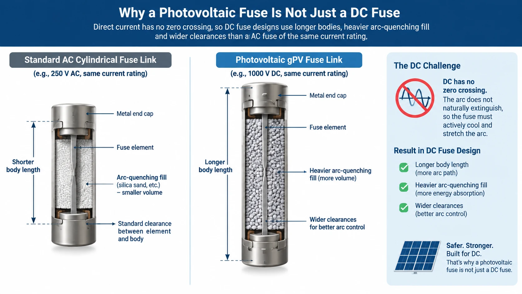
Direct current does not cross zero. In an AC circuit the arc that forms when a fuse element melts is helped out of existence roughly a hundred times a second by the natural zero crossing of the current. A DC arc has no such moment. Once struck, it keeps itself alive as long as the supply can push current through the ionised column, which is why DC fuse designs use longer bodies, heavier arc-quenching fill and wider clearances than an AC fuse of the same current rating.
Photovoltaic circuits add three complications on top of that:
Sustained low overcurrents. Partial shading, soiling and uneven string output produce small, persistent overloads rather than the sharp fault currents industrial fuses are usually sized around.
Reverse feed. A faulted string in a parallel array can be fed from the other strings, so fault current arrives from a direction the designer may not have considered.
Daily thermal cycling. A PV fuse spends its life warming and cooling with the sun, which is why IEC 60269-6 includes cycling tests that general-purpose fuse standards do not.
That is the difference between a gPV classification and a plain DC rating. A general-purpose DC fuse may carry the voltage number, but it has not been tested to the PV-specific duty cycle. If you want the underlying mechanism, our guide to why AC and DC fuses are not interchangeable covers the physics in more detail.
Step 1: Calculate the current the fuse has to carry
Start with the module datasheet, not with the array nameplate. You need the short-circuit current at standard test conditions, written as Isc.
Apply a design factor to convert that into a continuous current the fuse must carry without operating. IEC-guided design, including IEC 62548 and IEC 60364-7-712, commonly uses 1.25 × Isc. North American practice under NEC Article 690 applies further multipliers to account for continuous duty and irradiance above standard test conditions, so the effective factor there is higher. Use the factor required by the code edition in force for your project, and record which one you used.
Then multiply by the number of parallel strings the fuse is protecting, because in a parallel array each string’s fuse can carry the combined contribution of the others during a fault.
Worked example
Take a module with Isc = 13.0 A, with four parallel strings in a combiner box.
Step
Calculation
Result
Corrected string current
13.0 A × 1.25
16.3 A
Combined parallel current
16.3 A × 4
65.0 A
Next standard gPV rating above
—
80 A
Two things are worth noticing. First, the arithmetic pushes you upward, and the next standard rating is usually some distance away — fuse ratings come in fixed steps, not in continuous values. Second, this number is only the lower bound of the window. The upper bound is what usually decides the final choice.
Step 2: Find the upper bound before you order
A fuse that is too small nuisance-trips. A fuse that is too large does not protect the string. The upper bound comes from two sources, and the lower of the two wins.
The module’s maximum series fuse rating
Every PV module datasheet states a maximum series fuse rating, sometimes written as Irev max or “maximum overcurrent protection device rating”. This is the largest fuse the module manufacturer permits in series with that module. It is a module-specific number set by the manufacturer’s own testing, not a value you can derive from Isc. A 2 × Isc rule of thumb circulates in the field and sometimes lands close, but an assumed value is not a compliant substitute for the figure in the datasheet.
The string cable’s derated ampacity
The fuse also has to protect the cable. Cable ampacity is reduced by high ambient temperature inside the combiner box, by grouping with other current-carrying conductors, and by installation in conduit. Apply every derating factor that applies to the installation before using the number. If the derated ampacity falls below the module’s maximum series fuse rating, the cable becomes the binding constraint.
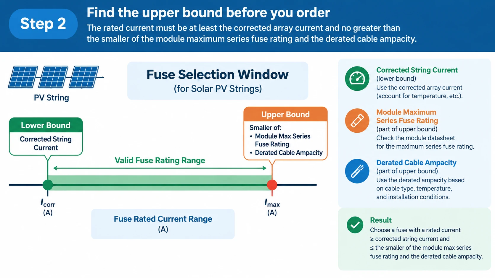
Put the two together and the selection window looks like this: the rated current must be at least the corrected array current from Step 1, and no greater than the smaller of the module’s maximum series fuse rating and the derated cable ampacity.
When the window has no solution
Occasionally the lower bound exceeds the upper bound and no standard fuse fits. That is a signal that the string design itself is out of balance, not a reason to pick the nearest fuse and move on. The usual fixes are to increase the cable cross-section so the derated ampacity rises, to reduce the number of parallel strings, or to specify a module with a higher maximum series fuse rating. Documenting a fuse that sits outside the window is how protection schedules end up non-compliant.
Step 3: Match the DC voltage rating to the cold-temperature voltage
Voltage rating is the parameter most often taken from the system label rather than from the circuit. Open-circuit voltage rises as cell temperature falls, so a string designed around 1000 V at standard test conditions can easily exceed 1000 V on a clear winter morning.
Read the module’s temperature coefficient of Voc from the datasheet, apply the lowest expected cell temperature for the site, and calculate the worst-case string Voc. The fuse’s DC voltage rating must be at or above that figure — not at or above the nominal system voltage.
This is also the point where 1000 V and 1500 V systems diverge in practice:
Consideration
1000 V DC system
1500 V DC system
Typical string length
Shorter, more strings per array
Longer strings, fewer combiners
Worst-case Voc at cold
Must stay under the fuse’s 1000 V DC rating
Must stay under the fuse’s 1500 V DC rating
Common fuse formats
10×38 mm, 14×51 mm, 22×58 mm gPV
14×85 mm gPV
Holder requirement
1000 V DC rated holder
1500 V DC rated holder
Consequence of using a 1000 V fuse
—
Arc may not clear; not a permissible substitution
A 1000 V DC fuse link in a 1500 V DC string is not a marginal choice. At the higher voltage the arc inside the body is easier to sustain, and a device that clears cleanly at 1000 V may fail to interrupt at 1500 V. Both the fuse link and the holder carry the voltage rating, and both have to match the system.
Step 4: Confirm the interrupting rating against the fault current
Breaking capacity — also called interrupting rating — is the maximum fault current the fuse can safely interrupt at its rated voltage. It has to exceed the prospective short-circuit current at the point of installation, calculated for the worst case the array can deliver.
The GD-13PV series, for example, carries a 20 kA breaking capacity with a 1–3 ms time constant, which suits string-level and combiner-box protection in the systems it is specified for. Whether 20 kA is sufficient in your installation depends on the array configuration and on what the inverter and upstream devices can contribute, so verify against your own fault study rather than assuming a generic figure. If the numbers involved are unfamiliar, fuse breaking capacity and voltage ratings explains how the two values interact.
Step 5: Match the fuse link to a DC-rated holder
The last step is mechanical and electrical at the same time. A fuse link and its holder must agree on four things: physical size, DC voltage rating, current rating and operating class. Agreement on size alone is not enough, and this is where project errors typically happen — a technician finds a 10×38 mm holder on the shelf, a 10×38 mm fuse link in the drawer, and assumes the pair is valid.
Fuse size
gPV fuse link
Matching PV holder
Voltage class
Typical duty
10×38 mm
GD-10PV / GD-12PV, up to 32 A
GDPV-32L
1000 V CC
String-level protection
14×51 mm
GD-14PV, 15–50 A
GDPV-50B
1000 V CC
Cajas de conexión fotovoltaicas
22×58 mm
GD-15PV series, 30–50 A
GDPV-22B
1000 V CC
1000 V DC string and array feeds
14×85 mm
GD-13PV, 8–50 A
GDPV-50 series
1500 V CC
High-voltage PV systems
The usable rating of an assembled pair is the lower of the two components, so a holder rated 32 A carrying a 50 A fuse link is a hazard, not an upgrade. The same logic applies to voltage: the pair takes the lower DC voltage rating. The full range of matched AC and DC combinations is listed on the fuses and fuse holders for AC, DC and solar applications page, which also covers what to send when you need a size the standard range does not include.
A worked example: for a 1500 V DC string requiring 25 A, the GD-13PV 25A fuse link is a 14×85 mm gPV device rated 1500 V DC with a 20 kA breaking capacity and IEC 60269-6 / UL 248-19 references. Its matching holders are the GDPV-50 series PV fuse bases, which accept 10×85 mm and 14×85 mm links and support 1000 V and 1500 V DC operation.
gPV, gG and aM: which class belongs in a PV circuit
Fuse class describes what the fuse is expected to interrupt, and mixing classes between an AC panel and a PV array is a common mistake when both are sourced from the same supplier.
Class
Full-range or partial-range
Intended duty
Belongs in a PV string?
gPV
Full-range
Photovoltaic circuits, tested to IEC 60269-6
Yes — this is the correct class
gG
Full-range
General distribution and cable protection, AC
No
aM
Partial-range
Motor circuits, must be paired with a overload relay
No
gR / aR
Full / partial
Semiconductor protection
Only where the equipment manual specifies it
A gG fuse may look electrically plausible in a PV string on paper, but it has not been tested to withstand the PV duty cycle and has no DC voltage rating as a photovoltaic device. The class marking on the fuse body is there for a reason, and the string-level device should read gPV.
Temperature, derating and nuisance operation
The rated current printed on a fuse link is established under specified reference conditions. A combiner box on a rooftop in summer commonly runs well above those conditions, and most PV fuse datasheets publish a temperature derating curve for exactly that case. Apply the manufacturer’s curve rather than a remembered percentage.
Two practical consequences follow. First, a fuse selected exactly at the lower bound of the window can operate repeatedly on hot days even though nothing is faulty — the answer is normally to check whether the derated ampacity of the cable allows a larger rating, not to bypass the protection. Second, loose terminals are a leading cause of localised heating in combiner boxes, and heat at the terminal raises the fuse’s operating temperature independent of ambient. Recheck terminal torque during routine maintenance before concluding that the fuse rating is wrong.
Common gPV fuse selection mistakes
Sizing on string operating current. Normal operating current is lower than the corrected worst case. Sizing on it produces a fuse that operates in good weather.
Using the module’s rated current instead of Isc. The relevant number is short-circuit current, corrected upward.
Reading voltage from the system label. Use worst-case string Voc at minimum cell temperature.
Assuming a DC rating is a PV rating. gPV requires testing to IEC 60269-6; a general DC rating does not cover it.
Matching fuse and holder by size only. Voltage, current and class all have to agree, and the pair takes the lower value of each.
Substituting a higher-rated fuse for nuisance operation. Persistent operation is a symptom. Find the cause — usually cable derating, a loose terminal, or a string design problem — rather than removing the protection.
Ignoring the module’s maximum series fuse rating. It is a hard upper bound set by the module manufacturer, not a suggestion.
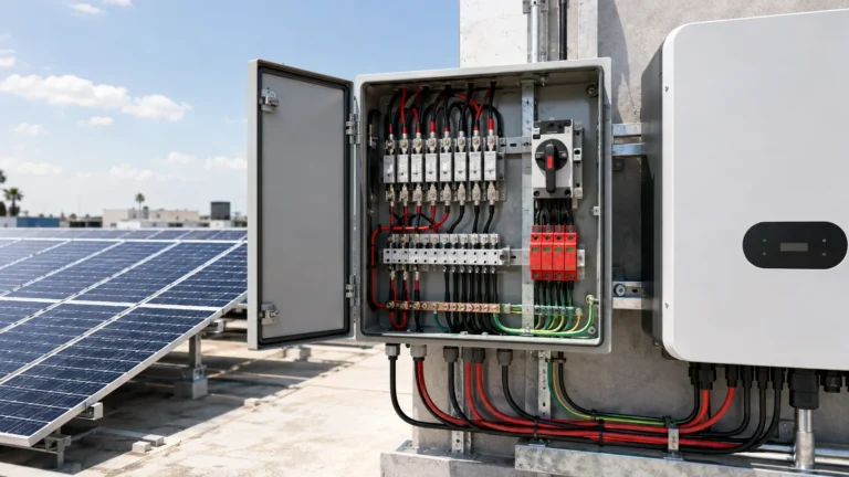
If the layout of the enclosure is unfamiliar — where the fuses sit, what they coordinate with, and how string protection is arranged — what a solar combiner box contains is a useful starting point before you get to fuse-level selection.
Frequently asked questions
What does gPV mean on a fuse?
gPV is an operating class for fuse links intended to protect photovoltaic circuits. It indicates the fuse has been tested to IEC 60269-6 for the current behaviour, reverse-feed conditions and thermal cycling that PV systems produce, rather than only to general-purpose fuse standards.
Can I use a 1000V DC fuse in a 1500V DC system?
No. The voltage rating of both the fuse link and its holder must be at or above the system’s worst-case DC voltage. A fuse rated below the system voltage may fail to extinguish the arc when it operates.
Should the fuse rating match the string current exactly?
No. The rating is chosen from a window: at or above the corrected array current and at or below the smaller of the module’s maximum series fuse rating and the derated cable ampacity. A rating equal to normal operating current would operate during normal high-irradiance conditions.
What is the difference between Irev max and the string current?
String current is what the array produces; Irev max, often called the maximum series fuse rating, is the largest fuse the module manufacturer permits in series with that module. One is a lower bound for fuse selection, the other an upper bound, and both come from the module datasheet.
Does a gPV fuse need a special holder?
It needs a holder with the matching physical size and an equal or higher DC voltage rating. A 1500 V DC gPV fuse link requires a holder rated for 1500 V DC; an AC holder of the same physical size is not a substitute.
Selection is a window, not a single number
Work the four values in order — corrected array current, module series fuse rating, derated cable ampacity and cold-temperature string voltage — and you end up with a window that a standard gPV rating either fits or does not. Then confirm the holder agrees on size, voltage, current and class, because the assembled pair only performs to the lower of the two components. If the window has no solution, the string design needs attention rather than a compromise fuse.
If you are specifying fuses for a PV project and have the string current, maximum system voltage, fuse size and estimated quantity to hand, the GA&DA team can confirm a matching fuse link and holder combination for your array.
Un protector contra sobretensiones limita las sobretensiones transitorias; un fusible interrumpe las sobrecorrientes. Conoce las diferencias, los límites de los dispositivos combinados y las comprobaciones necesarias para una protección coordinada.
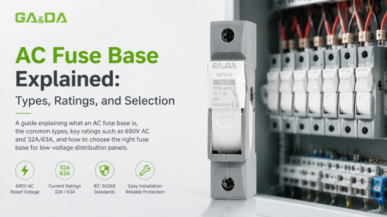
Una guía práctica sobre los soportes para fusibles de CA: para qué sirven, los tipos más habituales, las características técnicas más importantes y cómo elegir el más adecuado para tus cuadros eléctricos.
Aprende a leer un esquema de cableado de una caja combinadora solar, desde las entradas de las cadenas fotovoltaicas individuales y la protección mediante fusibles hasta las barras colectoras, el dispositivo de protección contra sobretensiones (SPD), la puesta a tierra, la agrupación MPPT y la conexión final al inversor.