Where to Install SPD in a Distribution Panel: Location, Wiring and Coordination
Yayın tarihi: Yazar: Rachel
Where a surge protective device is installed determines how much of the surge it actually intercepts. A correctly specified device placed in the wrong position provides far less protection than its datasheet suggests — and because the installation still looks compliant, the shortfall is rarely detected until equipment fails.
This guide covers surge protective device placement across a low-voltage installation: the main distribution board, sub-distribution boards, and final circuits, with specific sections on photovoltaic DC systems. It addresses positioning within the enclosure, upstream and downstream coordination, cable routing, and the specific cases where a single device cannot cover the whole installation.
İçindekiler
The Core Principle
Two properties of an SPD govern its effectiveness in a given position: its protection level Up, and the distance between the device and the equipment it protects. Both are in tension. Up is fixed by the device. Distance is fixed by the installation.
The reason distance matters is that surge transients propagate along conductors at a significant fraction of the speed of light. On unprotected cable, a transient can reach the far end before the reflected wave and initial travelling-wave conditions settle. The voltage the equipment actually experiences is not the device’s clamped value — it is higher, and rises with cable length.
This is the basis of the “10 m / 20 m rule” in IEC 61643-11: an SPD protects the equipment connected to it directly. Where the cable run exceeds approximately 10 metres, or routing exceeds approximately 20 metres through conduit or metal parts, a further protection level is required at the equipment.
Position 1: The Main Distribution Board
The main distribution board is the correct and most common location for Type 1 and Type 2 devices, for three reasons: it sits at the boundary between the lightning protection zones, it minimises unprotected cable length into the building, and it is the single point from which the largest proportion of circuits can be served.
Where the incoming supply is overhead, or the building has an external lightning protection system, this is where Type 1 devices belong — as close as practicable to the point where the conductors enter the building, before they run to the main switchboard.
Positioning within the board is not arbitrary. Three rules apply:
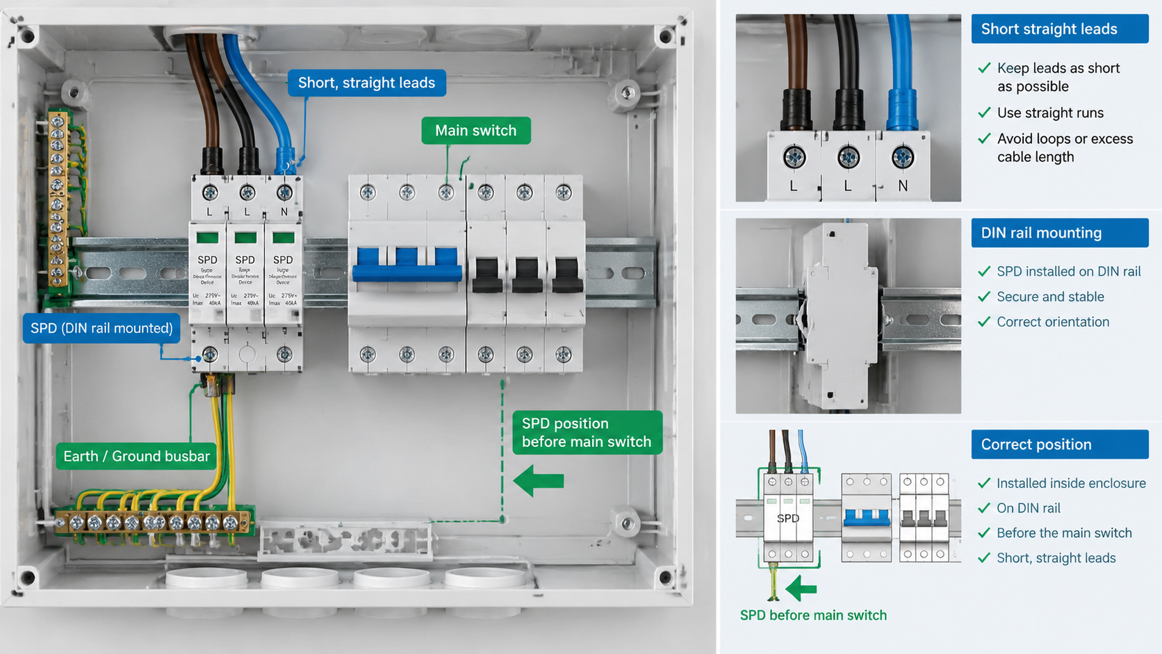
Before the main switch. The SPD must be on the load side of the main protective device, so that the incoming conductors are protected. Placing it after the main breaker leaves the section between the entry point and the breaker unprotected.
Short, straight, protected leads. Leads should be kept as short as practicable, routed to minimise loop area, and not shared with other conductors forming an inductive loop.
Correct position relative to the earthing bar. The protective earth terminal must connect by the shortest possible path to the device’s earth reference.
A common installation error is placing the SPD in a spare DIN position far from the incoming terminals, because the enclosure has room. This extends the unprotected run to several metres and negates much of the device’s benefit.
Position 2: Sub-Distribution Boards
Sub-distribution boards serve the practical purpose of extending protection to circuits that run too far from the main board to be effectively protected by it. They are particularly justified where:
Circuits run more than 10 metres from the main board
A separate building or outbuilding is supplied from the main installation
External cables run between buildings
Sensitive equipment sits at the end of a long internal run
The installation spans several lightning protection zones
A Type 2 device at the sub-distribution board protects everything supplied from it, in the same way the main board device protects its own circuits. Where the cable between main and sub-board is long and runs externally, Type 1 protection at the sub-board entry may also be required, since that cable presents its own induced-effect path.
Position 3: Final Circuits and Sensitive Loads
Individual sensitive equipment needs protection at the equipment itself when the run from the nearest adequate SPD exceeds the effective distance. This applies to network equipment, control systems, and electronics fed over long cables, particularly where the cable transits between buildings or runs near the external lightning protection system.
This position is where Type 3 devices apply, or plug-in / socket-level protection. The specification comparison here is the device’s Uoc against the equipment’s withstand voltage — not a current rating.
It is worth noting that protection close to the equipment cannot be retrofitted to equipment already installed deep in a cable run without significant cabling work. This is one of the stronger arguments for designing protection positions during initial installation rather than adding them afterwards.
Installation Within the Enclosure
Even with the right board chosen, position within the enclosure affects performance. The considerations are:
Proximity to line and neutral conductors. Both conductors must reach the device with minimal length and shared routing.
Avoiding loop formation. Incoming and outgoing conductors should not be routed parallel for long distances in the same trunking, as this increases the inductance through which the surge must discharge.
Separation from sensitive circuits. Surge currents in the protective earth should not share a path with signal or earth conductors for sensitive equipment.
Accessibility. The status window must remain visible for inspection without removing other components. This is a maintenance consideration, not a performance one, but devices that cannot be inspected are not monitored in practice.
Mounting orientation. For pluggable modules, orientation affects both the earth connection and, for some models, the rated performance.
Upstream and Downstream Coordination
Where devices appear at more than one position, they must be coordinated — not merely present. Two principles apply.
Upstream devices should have a higher current handling capacity than downstream devices. If a Type 1 device and a Type 2 device are both installed, the upstream device should be capable of absorbing the larger portion of the energy, leaving the downstream device to handle the residual. Upstream and downstream devices with identical protection levels risk the upstream device absorbing a surge intended for the downstream, then failing.
Protection levels should be consistent along the chain. A downstream device with a lower Up than the upstream device is generally desirable — the closest device to the equipment should provide the tightest clamping. Where this is inverted, the downstream device offers no additional protection.
GA&DA’s Type 1 and Type 2 range spans current ratings from 20 A to 120 A, which allows upstream and downstream devices to be selected within the same product family and coordinated without cross-referencing unrelated datasheets.
Cable Routing and Lead Length
Every metre of lead between the surge current and the device reduces its effectiveness. Manufacturers specify device performance at a stated maximum lead length, typically 1 metre for the connection to the protective earth terminal. Exceeding this does not invalidate the device, but it means the installed protection level is higher than the datasheet value.
Best practice for connection leads: keep them short, route them straight, avoid running them parallel to the conductors they protect over long distances, and separate them from any earth conductors used by other equipment. Where the earth lead must be longer than one metre, the consequence should be documented.
Photovoltaic DC Installation
PV DC systems need their own surge protection arrangement, and the installation logic differs from the AC side because of where the cable runs and how it is generated.
PV string cables run outdoors, often over distances of tens of metres, and are therefore exposed to induced effects along their entire length. Protection must be applied at the point where the DC circuits enter the building, and — because PV cables are frequently routed externally to a separate inverter location — at that equipment as well.
At the combiner box — a Type 2 PV-rated SPD, typically already integrated in a specified combiner box assembly, protects the strings and their terminations.
At the building entry point — where DC cables pass from external to internal routing, a second SPD protects the internal section.
At the inverter input — where the DC run exceeds the effective distance, protection should be fitted at the inverter, not only at the combiner box.
DC-specific requirements that must be observed:
Dedicated DC backup protection. The SPD’s Uc must match the system DC voltage, and a DC fuse or disconnection device must be coordinated so a failed SPD can be isolated.
DC rating, not AC. DC arc interruption differs fundamentally; an AC-rated device is not suitable.
Placement before the DC switch. As on the AC side, the SPD belongs on the load side of the DC disconnect so the conductors between entry and switch are protected.
Polarisation and string configuration. Multi-string combiners require SPDs on all live conductors, not a single common pole.
GA&DA’s PV-specific surge protective devices, including the G2015PV-BC and G2040PV-BC series, are rated and tested for DC photovoltaic applications and are supplied with the coordination requirements in mind. See also the güneş enerjisi birleştirici kutusu range, where SPD and fuse protection are specified together.
Earthing and Bonding
An SPD requires a low-impedance path to earth to discharge the surge current. This is not a secondary consideration: a device without an effective earth reference cannot perform its function, and a poor earth connection is a safety issue in its own right.
Connect the device’s earth terminal by the shortest practicable route to the enclosure’s earth bar.
Use a conductor of adequate cross-section for the expected surge current, and keep this conductor separate from functional and protective earth conductors of other circuits where possible.
Confirm the continuity of the earth path from the device to the installation’s main earth terminal.
For Type 1 devices on buildings with an LPS, the protective earth and the LPS earth electrode system must be coordinated so surge currents are not routed through the building’s earth electrode in ways that affect other services.
How Many Devices Do You Need?
A working rule of thumb, subject to the LPZ assessment:
Minimum viable installation — Type 2 at the main distribution board, coordinated backup protection, effective earth connection.
Building with external LPS or overhead supply — Type 1 at the entry point plus Type 2 at the main board.
Multi-building or long external runs — the above, plus Type 2 at each receiving sub-board entered by an external cable.
Sensitive equipment on long circuits — plus protection at the equipment itself, Type 3 or plug-in as appropriate.
Photovoltaic installation — Type 2 PV-rated at the combiner box and at the building entry, plus protection at the inverter where the DC run is long.
The common thread is distance. The number of devices required follows from the cable lengths between them and the equipment being protected, not from a fixed rule.
Inspection and Verification
Installation is only the first step. Protection degrades over time and the failure mode is usually silent.
Status indication. SPDs use a mechanical or electronic indicator that shows operational state. These should be checked at defined intervals and after any event that might have caused a surge.
Replacement procedure. The correct replacement procedure must be known before the need arises — incorrect replacement leaves the circuit unprotected or the device unable to clear a fault.
Remote monitoring. Where continuity of supply makes visual checks impractical, remotely monitored SPDs report status to a building management system.
Records. SPD coordinates, ratings, and installation dates should be recorded, since this information is needed when a replacement device must be specified compatibly.
Related GA&DA Products
GA&DA supplies Type 1, Type 2, and Type 3 surge protective devices for AC and DC applications, including PV-specific models, in current ratings from 20 A to 120 A to support upstream/downstream coordination within a single product family. See the full aşırı gerilim koruma cihazları range. DC circuit breakers and fuse links are available for the backup protection positions described above, and solar combiner boxes specify SPD and fuse protection together for photovoltaic systems.
Certification requirements sit between a solar combiner box being technically suitable and being accepted. In practice, a box that meets every functional requirement can still be rejected at tender stage or on site because the documentation supporting its conformity does not match what the market expects. This is a documentation and compliance topic rather than […]
Most solar combiner box datasheets open with a table of ratings, and most buyers skim past it. That table is where the decision actually gets made. A combiner box is a passive enclosure — it does not protect anything by itself — so every number on its datasheet is either a limit you must stay […]
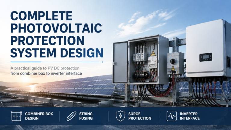
Photovoltaic systems fail in ways that are individually simple and collectively expensive. A DC arc that never clears. A fuse that blows on a cloudy morning. A surge that enters through the PV cable rather than the mains. Each of these sits on the DC side, and each traces back to a protection decision made […]