Type 1 vs Type 2 Surge Protective Devices: Key Differences and Applications
Yayın tarihi: Yazar: gandian-ye
The difference between a Type 1 and a Type 2 SPD is the surge it is built to survive. A Type 1 device is tested with a 10/350 µs lightning current waveform and is installed at the service entrance, where a lightning current can enter the installation. A Type 2 device is tested with an 8/20 µs waveform and is installed in distribution boards downstream, where it handles induced surges and switching transients.
That single sentence explains most of the practical differences that follow: why the two are rated in different units, why their current numbers cannot be compared directly, why one belongs at the incoming panel and the other does not, and why a Type 2 device cannot simply be substituted where a Type 1 is required.
The rest of this article covers the comparison properly — the waveforms, the ratings, the installation points, the combined Type 1+2 devices that many projects actually buy, and the decision path for specifying one or the other.
Type 1 vs Type 2: Side-by-Side Comparison
Property
Tip 1 SPD
Tip 2 SPD
IEC 61643-11 class
Class I
Class II
Test waveform
10/350 µs (simulated lightning current)
8/20 µs (simulated induced / switching surge)
Characteristic rating
Iimp — impulse current, kA
In nominal and Imax maximum discharge current, kA
Installation point
Service entrance / main LV board, at the LPZ 0→1 boundary
Main or sub-distribution boards, at LPZ 1→2 and downstream
Handles partial lightning current
Yes, by design
No — not its tested duty
Technology
Spark gap, high-energy varistor, or hybrid
Metal oxide varistor (MOV), usually plug-in modules
Typical Up
Higher, because energy handling comes first
Lower, because clamping performance is the point
Needs upstream protection
Often not, if tested for it; otherwise per datasheet
Usually yes — fuse or MCB sized per datasheet
Can be used alone
Yes, but downstream equipment stays exposed to residual surges
Yes at distribution level, provided no lightning current enters there
What the Two Test Waveforms Actually Mean
The numbers 10/350 ve 8/20 describe the shape of a current pulse: the first figure is the rise time to peak in microseconds, the second is the decay time to half peak.
A 10/350 µs pulse is slow and massive. It represents a lightning current — the kind that arrives when a strike hits an overhead line directly, or when the external lightning protection system diverts current through the installation. The energy in that pulse is orders of magnitude above anything switching produces, which is why a Type 1 device needs heavier internal components and a housing that survives the electrodynamic force of the event.
An 8/20 µs pulse is fast and much smaller. It represents what happens when lightning strikes nearby rather than on the line, or when a large load switches: a short, steep transient that still carries enough energy to destroy a power supply but nothing like a full lightning current.
Because the waveforms differ, the kA figures on the two datasheets are not on the same scale. A Type 1 device rated at 25 kA Iimp is not “smaller” than a Type 2 device rated at 40 kA Imax — they are describing different tests on different pulses. Comparing the two numbers directly is one of the most common specification errors in surge protection.
Where Each Device Belongs in the Installation
IEC 62305-4 describes the installation as a series of lightning protection zones. Every time a conductor crosses a boundary between zones, the surge energy has to be reduced before it continues. The SPDs are the devices that do the reducing, and their position is determined by the boundaries, not by panel layout convenience.
LPZ 0→1 at the service entrance. This is where current from the external network and from the lightning protection system enters. A Type 1 SPD sits here because this is the only point where a partial lightning current can be expected.
LPZ 1→2 at main and sub-distribution boards. The residual surge from stage one, plus locally generated switching transients, arrives here. Type 2 SPDs reduce it further and are typically installed in every board that feeds critical loads.
LPZ 2→3 at the equipment. Type 3 devices sit beside the load, on the same DIN rail or feeding the same final circuit, and bring the residual voltage below what the equipment can withstand.
The practical rule: a Type 2 SPD in a distribution board is normal; a Type 2 SPD where a Type 1 is required is a design error, because there is no device in the chain that was ever tested for a lightning current. Conversely, a Type 1 device alone at the entrance leaves everything downstream exposed to the residual that the Type 1 lets through.
The Ratings That Actually Differ
Iimp (Type 1 only). The peak current the device can discharge on a 10/350 µs waveform, per pole. It is the defining number for a Type 1 device. Sites with overhead supply, an external lightning protection system, or a high flash density need a higher value; a fully underground urban supply may justify a lower one, decided by the risk assessment rather than by habit.
In and Imax (Type 2). In is the current the device can handle repeatedly, 20 times, without degrading. Imax is the single-shot limit it can survive once. A device with a high Imax but a low In looks impressive on a datasheet and wears out faster in service — for an industrial board with frequent switching, In is the more useful figure.
Uc, maximum continuous operating voltage. Must sit above the highest sustained voltage the system can present, including tolerance. Getting this wrong shows up as nuisance trips or, worse, as a device that fails thermally with no surge present.
Up, voltage protection level. The residual voltage left at the terminals at the rated discharge current. This is the number that decides whether the equipment survives, and it must be lower than the equipment’s impulse withstand voltage. For a 230/400 V installation the reference values are the overvoltage categories: 1.5 kV, 2.5 kV, 4 kV and 6 kV depending on where in the installation the equipment sits.
Coordinating the two stages means each downstream device clamps at or below the level of the one upstream. If the Type 2 device has a higher Up than the Type 1 ahead of it, the arrangement is not doing what the drawing claims.
Type 1+2 Combined Devices: When One Box Is the Right Answer
Many projects do not buy two separate devices. A Type 1+2 SPD is tested on both waveforms and is installed at the service entrance, covering the entrance and the first distribution level in one unit.
It makes sense in three situations:
Panel space is limited and a second device would mean a new enclosure.
The distance from the entrance to the first distribution board is short — under roughly 10 m — so a separate second stage adds little.
The installation is small enough that a single entrance-level device with good Up covers the whole load list.
What a combined device does not do is remove the need for Type 3 protection at sensitive equipment, or for a dedicated Type 2 in a remote board several floors away. Combining stages in one housing is a space decision, not a reason to stop counting zones.
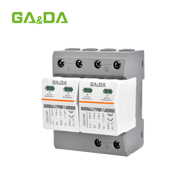
For the device range itself, the SPD product line covers Type 1, Type 2 and combined units in DIN-rail modular form, and the Type 1, 2, 3 selection guide works through the ratings for each stage.
How to Decide: Four Questions
Can lightning current reach this point? Overhead supply, an external lightning protection system bonded to the installation, or a structure in a high-flash-density area: yes, so a Type 1 is required at the entrance. Fully underground supply with a low risk assessment: a Type 2 at the main board may be the correct minimum.
What is the equipment’s withstand voltage? Compare Up against the overvoltage category of the load. If the margin is thin, add a downstream stage rather than buying a bigger single device.
How far is the board from the entrance? Long cable runs between stages reduce coordination, and short runs make a combined device attractive.
What does the local code require? National requirements are not uniform — some mandate SPDs in certain occupancies, others leave it to risk assessment. The code question is settled first, because it decides whether the other three are optional.
Coordination Between the Two Stages
Two SPDs in series do not automatically share the work. Coordination depends on the impedance between them, which in practice means cable length.
The usual engineering guidance is a minimum of about 10 m of cable between a Type 1 and the Type 2 downstream of it, or the use of a decoupling element where that length is not available. Without it, the downstream device sees the full surge and does the work the upstream device was specified for — which is how a Type 2 module ends up destroyed while the Type 1 next to it is untouched.
Both stages also need their short-circuit withstand to match the prospective fault current at that point, and where the manufacturer specifies backup protection, the fuse or breaker rating and curve have to be followed. This is covered in more detail in the guide to SPD backup protection.
The UL Naming Trap
UL 1449 also uses the labels “Type 1”, “Type 2” and “Type 3”, and they do not mean the same thing as the IEC classes.
Under IEC 61643-11 the class is set by the test waveform — the energy the device is designed to absorb. Under UL 1449 the type is largely set by where the device is installed and whether it needs external overcurrent protection. The result is that a device can be UL Type 1 and IEC Type 2 at the same time, and a CE-marked IEC Type 2 device may have no UL listing at all.
For a project in North America, the UL listing and the SCCR rating are what the inspector looks for, not the IEC class. For a project specifying IEC or EN, the IEC class is the reference. A supplier that cannot state both clearly is a supplier to ask harder questions of.
Installation Rules That Decide Whether Either Device Works
A correctly specified SPD with a long, looped connection is a badly performing SPD. The connecting leads add inductance, and the voltage across that inductance appears on top of the device’s Up at the exact moment it matters.
Keep the total lead length from busbar to device to earth bar as short and straight as possible. Under half a metre is good practice; over a metre starts to erode the rating you paid for.
Bond the SPD earth terminal to the main earth bar directly, not through the enclosure.
Do not run protected and unprotected conductors in the same bundle.
Check the status indicator at every maintenance visit, and record it. A red window is end of life, not a fault to investigate later.
Sık Sorulan Sorular
Do I always need both a Type 1 and a Type 2 SPD?
No. It depends on whether lightning current can reach the installation. An overhead supply or a bonded external lightning protection system normally requires a Type 1 at the entrance, with Type 2 downstream. A fully underground supply with a low-risk assessment may justify starting at Type 2. Most commercial and industrial installations end up with both, or with a combined Type 1+2 device.
Can a Type 2 SPD replace a Type 1 at the service entrance?
No. A Type 2 device is tested on an 8/20 µs waveform and is not rated for a partial lightning current. Where a Type 1 is required and a Type 2 is installed instead, the device may fail during a severe event, and the installation is unprotected at the exact point where the energy is highest.
Should I prioritise the kA rating or the protection level Up?
At the service entrance, energy handling comes first, which is why Type 1 devices are specified there. Closer to the load, Up becomes the deciding number, because it determines whether the equipment’s withstand voltage is respected. In a cascaded design both matter, at different stages.
How do I know when to replace an SPD?
Check the status indicator. Most modular SPDs show green for healthy and red for end of life, and many provide a remote contact that can be wired to a BMS or alarm. Replacement is module-only on plug-in designs, so there is no need to rewire the enclosure.
Is a Type 1+2 device as good as two separate devices?
It solves the same two stages in one housing when the distance between the entrance and the first distribution board is short. It does not remove the need for Type 3 protection at sensitive equipment, or for a separate Type 2 in a board far from the entrance.
If you are choosing between the two for a specific panel, send the system voltage, earthing arrangement, whether the supply is overhead or underground, and the equipment you need to protect. We will reply with the stage arrangement and the rating range that fits it, rather than a single catalogue number.
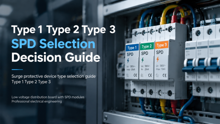
Selecting the wrong surge protective device type is one of the more common and more expensive specification errors in low-voltage installations. The device may work, the installation may pass inspection, and the system will still be under-protected for the actual risk it faces — because Type 1, Type 2, and Type 3 devices are not […]
Follow a DC surge protection circuit through normal operation, a surge and recovery, and see why protection modes and DC fault disconnection need their own design.
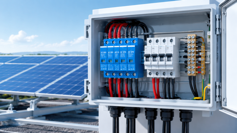
Çoğu güneş enerjisi DC dağıtım kutusu (DCDB), 8/20 µs dalgalanma akımlarına uygun Tip 2 DC dalgalanma koruma cihazı (SPD) ile donatılmıştır; DC devresinin doğrudan yıldırım çarpmasına maruz kalması veya tesisin harici bir yıldırım koruma sistemine sahip olmaması durumunda Tip 1+2 DC SPD gereklidir. Bu kılavuzda, nasıl karar verileceği açıklanmaktadır […]