Solar Combiner Box vs Junction Box: Are They the Same?
Publié le : Auteur : Rachel
“Combiner box vs junction box” is one of the most common points of confusion in PV design, and it is not a cosmetic one. The two enclosures look similar on a wall, are both described loosely as “the box where the strings are terminated”, and are not interchangeable. A junction box is a passive termination point. A combiner box is a termination point, a paralleling point and a protection point in the same enclosure. Which one your design needs is decided by string count and inverter MPPT architecture, not by enclosure price alone.
This article compares the two on function, protective content, enclosure class, string count and MPPT architecture, how codes treat them, substitution risk, cost and complexity, and finishes with worked examples for a small rooftop and a commercial array. The device itself is explained in what is a solar combiner box — this article assumes you already know what a combiner does and deals only with the choice between the two boxes.
Safety First: Both Boxes Sit on a Live DC System
Everything below is a design discussion. Neither enclosure can be opened safely without a procedure, and a small junction box is exactly as dangerous as a large combiner enclosure because the conductor voltage is the same.
PV arrays are live in daylight. There is no off switch on a module, and a disconnected string still carries full open-circuit voltage.
Isolate, verify dead, then work. Prove the tester on a known live source before and after the test.
Do not work on energised PV strings. Insulation-resistance, polarity and continuity checks require the strings isolated at both ends.
Wear arc-rated PPE and insulated gloves. A DC arc does not self-extinguish at a current zero, so a DC side fault is harder to clear than the equivalent AC fault.
The One-Line Difference
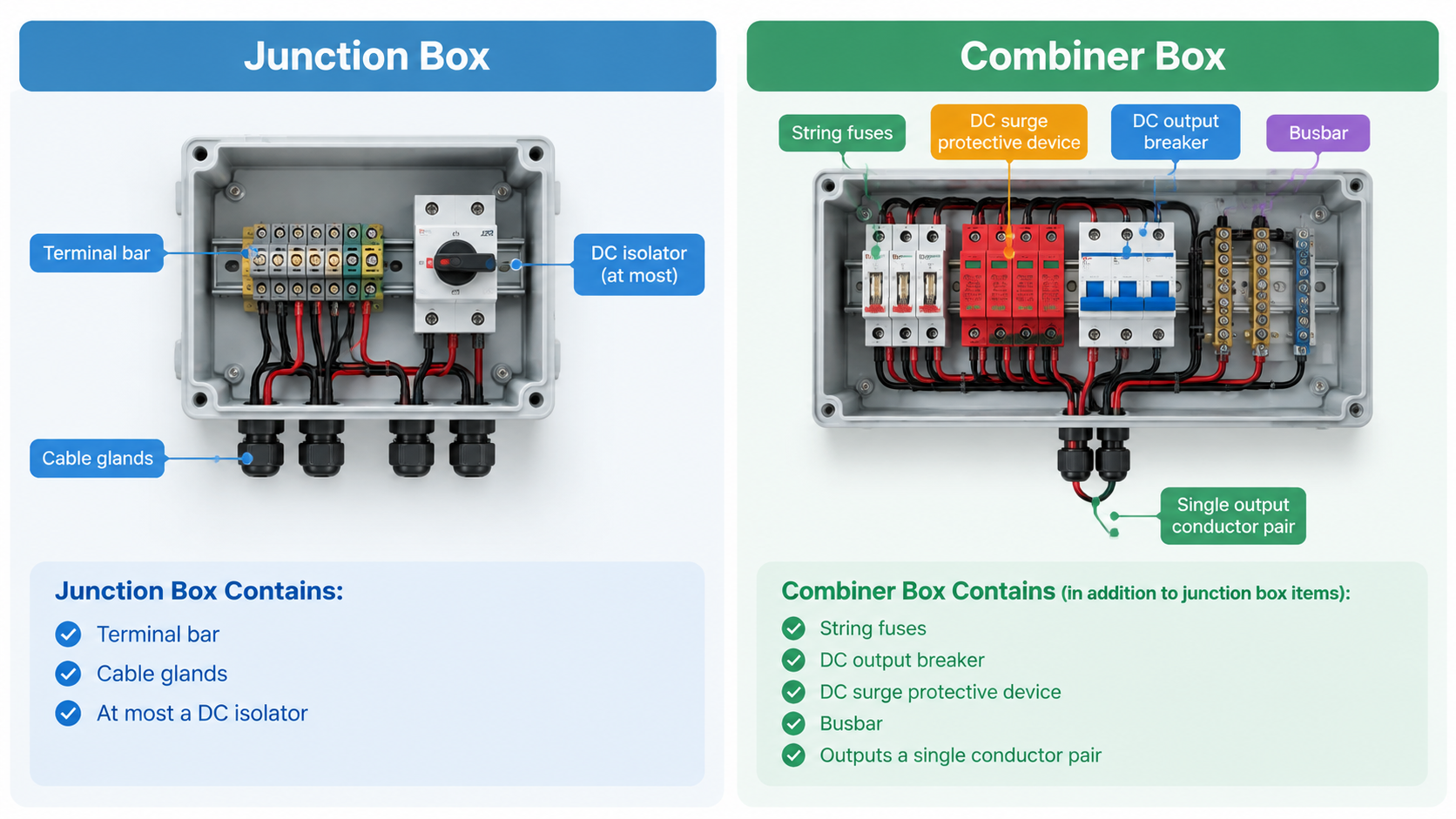
A junction box (also called an array junction box or string junction box) joins and terminates conductors. String pairs come in, string pairs go out. Its job is mechanical and environmental: keep the joint dry, keep it tight, keep it identifiable, and sometimes provide a local isolation point through a DC isolator. It does not change how many current-carrying conductors reach the inverter, and it does not normally contain anything that interrupts a fault.
A combiner box does all of that and adds two functions. It parallels several strings onto one busbar so that one outgoing conductor pair leaves the enclosure, and it protects the strings and the combined output with string fuses, an output DC breaker or switch-disconnector, and usually a DC surge protective device.
That is the whole distinction, and every practical consequence follows from it.
Function-by-Function Comparison
Question
Junction box
Combiner box
Primary purpose
Join, terminate and protect conductors from the environment
Parallel strings and protect them, then feed one output pair
Conductors in / out
n string pairs in, n string pairs out
n string pairs in, one pair out
Paralleling point
No — there is no combined circuit
Yes — the busbar
String fuses
Normally none
Normally one per string leg as the design requires
Output device
None, or an isolator only
DC breaker or switch-disconnector on the combined output
DC SPD
Rarely, and only where specifically designed in
Commonly, protecting the combined output
Effect on inverter DC inputs
None — every string still arrives at the inverter
Reduces the number of DC inputs required
Typical string capacity
Small — a handful of string pairs
Larger — from a few strings up to a full array group
Per-string monitoring
Not available
Common on larger units
Do They Contain Protective Devices?
This is the question that decides most arguments, so answer it from the one-line diagram rather than from the enclosure.
Junction box: typically no overcurrent protection at all. It may contain a DC isolator, which is a switching device and not an overcurrent device, and it may contain terminations and a small earth bar. If you see a fuse holder inside a box described as a junction box, you are looking at a small combiner box regardless of what the label says.
Combiner box: by definition it contains the protection for the strings it groups — string fuses and holders, an output device, and in most PV designs a DC SPD. The internal arrangement, and which pole is fused, is covered in our solar combiner box wiring diagram guide.
Same enclosure technology, different contents: the combiner box adds fuses, an output device and an SPD on the combined circuit.
One habit worth building: treat any device that has operated as a symptom rather than a fault. A blown string fuse or a tripped DC breaker in a combiner box tells you a fault existed somewhere on that string. Re-energising it repeatedly without diagnosing the cause is how a small insulation fault becomes a fire.
Enclosure Class and Environment
Both boxes live outdoors for twenty years or more, so both need to be selected for the actual site, not for the catalogue. The difference is that a combiner box has more to lose from a bad enclosure decision.
Ingress protection. Both should be rated for the environment and installed so the rating survives — correct gland sizing and a properly seated gasket matter more than the number on the label. Confirm the claimed degree against the manufacturer’s datasheet, and note that IP alone does not prevent internal condensation.
Internal heat. Fuses, holders, a breaker and an SPD all dissipate heat inside a combiner box, and at high ambient that heat derates the very devices protecting the strings. A junction box with terminations only runs cooler, which is one reason a combiner box is usually larger and better ventilated.
Corrosion and UV. Coastal, agricultural and desert sites attack gaskets, fixings and metallic parts, so enclosure material matters as much as the IP number.
Bonding and earthing. A metallic enclosure needs bonding, and a combiner box needs an earthing bar because the SPD depends on a short, low-impedance path to earth. Confirm the requirement against your local wiring rules.
Terminal and busbar capacity. The quiet failure mode when a junction box is pushed beyond its role: terminals rated for string current are not rated for the summed current of several strings.
String Count and MPPT Architecture Decide the Answer
Forget the box for a moment and look at the array. Two numbers decide everything.
1. How many strings do you have?2. How many independent MPPT inputs does the inverter provide?
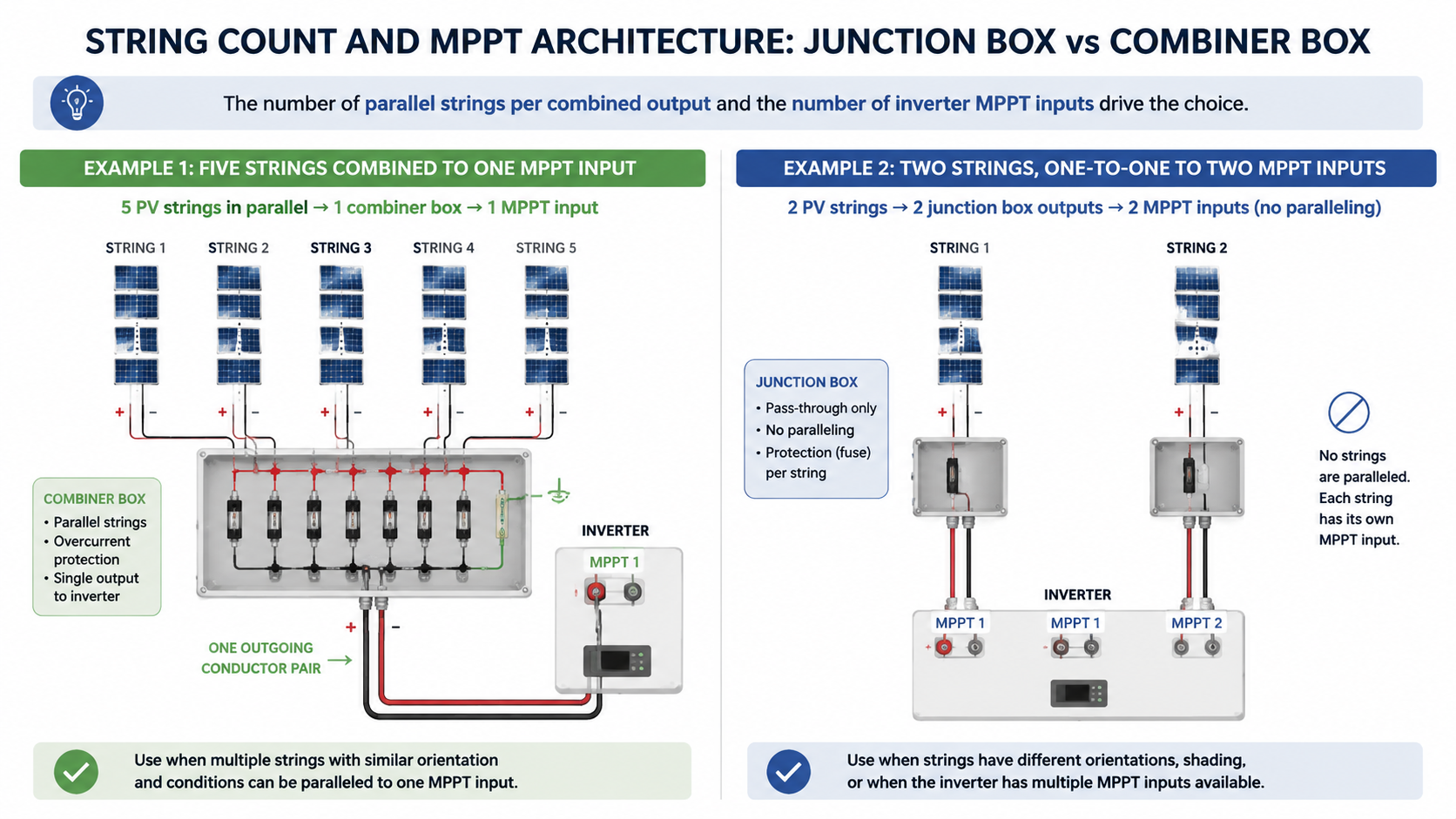
If the answer is one string per MPPT input, nothing needs to be paralleled at the array. There is no combined circuit, so there is nothing for a combiner box to combine. A junction box that terminates the string conductors and provides the local isolation point is the correct answer.
If you have more strings than MPPT inputs, you either run several conductor pairs to the inverter and parallel them there, or you parallel them at the array. Paralleling at the array is what a combiner box does, and once you parallel strings a second issue appears: a faulted string can be back-fed by the healthy ones.
For n strings in parallel, the potential back-feed into one faulted string approaches (n − 1) × Isc. Compare that with the module manufacturer’s maximum series fuse rating and with the current-carrying capacity of the string cable. Where the back-feed can exceed those limits, the string needs overcurrent protection — and that protection belongs in a combiner box. The full sizing method, including voltage and current checks, is in Dimensionnement des boîtiers de raccordement photovoltaïques.
There is a performance consequence too. Strings paralleled onto the same MPPT input share one maximum power point, so strings on different orientations or with different shading patterns will drag each other down. Group strings by orientation and shade profile, not just by count.
One string per MPPT input needs no paralleling; five strings on one input need a combined, protected output — the combiner box case.
How Codes and Standards Treat the Two Boxes
Code treatment is jurisdiction-dependent, and the terminology differs between them. North American practice uses the vocabulary of PV source circuits and PV output circuits and the term “combiner”; IEC-derived national codes and other regional rules use different terms and sometimes different thresholds. Verify every requirement against the code edition and local amendments that apply to your project, and confirm the interpretation with the local authority before you buy the enclosures.
What is consistent across mature codes is the underlying principle, and that principle is what should drive your design:
Where PV source circuits are connected in parallel, a fault on one circuit can be fed by the others. Codes generally require protection to interrupt that back-feed, which is why string overcurrent protection is tied to parallel connection and not to enclosure type.
A means of disconnection and isolation is required at defined points, and it must be labelled and accessible to the people who need it.
Enclosures must suit the environment and be installed per the manufacturer’s instructions.
Modules and cables must be protected within their ratings, which is why the module datasheet’s maximum series fuse rating ends up in the calculation.
Two practical notes. First, some wiring rules use “junction box” as a defined term for a box used only to join conductors, so describing a combiner box that way on a drawing can cause an inspection argument — use the terminology your jurisdiction uses. Second, a junction box may be electrically possible in place of a combiner box and still be non-compliant.
When a Junction Box Is Sufficient
One string per MPPT input, so no paralleling occurs anywhere in the array.
Small systems where the only requirement is terminating module cable onto array cable and providing a local isolation point.
Installations where the inverter has enough DC inputs for every string, including a spare for future expansion.
Anywhere the local code does not require string overcurrent protection because no source circuits are connected in parallel.
A junction box is not a “cheap combiner box”. It is the correct device for a design that never combines anything, and it is usually the neater solution in that case because there is no unused protection hardware to maintain.
When a Combiner Box Is Required
You have more strings than the inverter has MPPT inputs, or than you are willing to use.
Several strings are connected in parallel on one circuit, so back-feed protection is needed.
The run from array to inverter is long and you want one conductor pair per group instead of one pair per string.
You want a single isolation point for a group of strings for maintenance and safe isolation.
You want a DC SPD at the array rather than relying on protection at the far end of a long cable run.
You want per-string current visibility to find an underperforming string quickly.
Can You Substitute a Junction Box for a Combiner Box?
Direct answer: not if the design depends on paralleling or on string protection. If your strings are paralleled anywhere, the protection that accompanies paralleling has to exist — the enclosure is just where it lives. Moving the paralleling point into a plain junction box does not remove the need for the protection; it removes the protection.
What the design needs
What a junction box provides
Consequence of substituting
Parallel connection of source circuits
Terminals and joints only
You must parallel at the inverter, or abandon the architecture
Overcurrent protection for back-feed
No overcurrent device
A faulted string keeps being fed by the healthy strings; damaged modules, cable and connectors
A single isolation point for a group
Per-string isolation at best
Slower, less verifiable isolation; higher risk of working on a partly live system
Surge protection at the array
Usually absent
Surge energy travels further into the installation before it is clamped
Terminals rated for the combined current
Rated for individual string currents
Overheating and progressive terminal damage under continuous load
Code-compliant protection of paralleled circuits
Not designed for it
Failed inspection, rework at your cost, and a design liability that outlives the project
The one substitution that is legitimate is the reverse direction: using a combiner box in a role that technically only needed a junction box. It costs more and adds devices to maintain, but nothing is unsafe or non-compliant about it.
Cost and Complexity Trade-Off
Do not compare the price of two enclosures. Compare the installed cost of two architectures, because the enclosure is usually the smaller part of the difference.
Cost or complexity factor
Junction box architecture
Combiner box architecture
Enclosure and devices
Lowest
Higher — fuses, holders, breaker, SPD, busbar
DC cable to the inverter
One pair per string
One pair per combined group
Inverter DC inputs needed
Equal to string count
Equal to group count
Termination labour
Mostly at the inverter
Mostly in the field enclosure
Fault finding
Depends entirely on inverter diagnostics
Per-string current comparison at the box
Maintenance isolation
Per string or at the inverter
One operation per group
Future expansion
Add a string if inputs remain
Needs a spare way or another box
Typical outcome
Cheaper for one or two strings and short runs
Cheaper once string count and cable length rise
The trade-off is therefore not “cheap versus good”. It is “spend on cable and inverter inputs” versus “spend on a protected field enclosure”. Copper and labour usually dominate at scale, which is why commercial arrays almost always combine.
Worked Example A — Small Rooftop Array
All values below are illustrative. Substitute the actual module, inverter and cable data for your project and verify against the datasheets and local code.
Array: 24 modules × 500 Wp = 12 kWp.
Configuration: 2 strings of 12 modules in series.
Illustrative module data: Voc 49.5 V, Isc 13.0 A, maximum series fuse rating 25 A.
String voltage at STC: 12 × 49.5 V = 594 V. The cold-temperature corrected Voc must still be checked against the inverter maximum input voltage and the DC rating of the string components.
Inverter: 2 MPPT inputs.
Two strings, two MPPT inputs. Each string goes to its own input, so the strings are never connected in parallel. There is no combined circuit, no back-feed path, and therefore no case for string overcurrent protection on the array side.
Correct choice: a junction box at the array, with a DC isolator. A combiner box would work here, but it would add fuses, a breaker and an SPD that do nothing this design needs, plus more terminals to torque and inspect for the next twenty years.
What still has to be provided regardless of which box you fit: a means of isolation at the array, polarity and string labelling, bonding of any metallic enclosure, cable sized for the run and the installation method, and a check of the cold-temperature string voltage against the inverter limit.
Worked Example B — Commercial Array
Same illustrative module data as above. Real projects must use the actual datasheets and the local code edition.
String voltage at STC: 25 × 49.5 V = 1237.5 V, which must be verified against the 1500 V DC rating of the fuses, SPD, breakers, cable and connectors after cold-temperature correction.
Inverter: 6 MPPT inputs.
Twenty string pairs cannot connect directly to six inputs. The design groups the strings: 4 combiner boxes with 5 string inputs each = 20 strings, giving four output pairs into four of the six MPPT inputs.
Now run the back-feed check that a junction box cannot answer. With five strings paralleled on one combined output, a single faulted string can be fed by the other four at approximately (5 − 1) × 13.0 A = 52 A. That is more than twice the 25 A maximum series fuse rating of the module, and it is the reason string overcurrent protection is required here. The fuse must be selected from the string’s Isc and the module’s maximum series fuse rating, then corrected for the ambient temperature inside the enclosure.
What the combiner boxes buy on this project:
Twenty string pairs become four pairs on the long run to the inverter — a large reduction in copper and in cable-tray fill.
Back-feed into a faulted string is interrupted by the string fuse instead of being carried by the module and its cable.
One DC SPD protects each group close to the array instead of one device far away.
Per-string currents can be compared to find a failing string in minutes rather than by climbing the roof.
Isolation for maintenance is one operation per group.
Two design cautions. Group the five strings on each MPPT input by orientation and shading so they share a genuinely common maximum power point. And size the boxes, busbars and output devices for the combined current rather than for one string — this is the step where under-specified enclosures fail. Layout guidance for this scale is in PV combiner box for commercial solar.
Selection Checklist
Count the strings and the available MPPT inputs.
If they match one-to-one, plan junction boxes and no string protection.
If they do not match, decide where the paralleling happens and design the protection for that point.
Calculate the back-feed current for the parallel group and compare it with the module’s maximum series fuse rating and the cable rating.
Decide whether you want the DC SPD and the isolation point at the array or at the inverter.
Compare total installed cost, including cable, inverter inputs, termination labour and maintenance access.
Verify the whole design against the local code edition and confirm it with the authority before ordering.
If you are specifying enclosures for a project and want the two architectures priced against the same scope, our solar combiner box range covers the combined-output designs, and you can send the array details through to our engineers for a comparison against a junction-box layout.
Frequently Asked Questions
Is a combiner box the same as a junction box?
No. A junction box only joins and terminates conductors. A combiner box does that as well, but it also parallels several strings onto one output and houses the devices that protect them. If it contains string fuses or a combined output device, it is a combiner box whatever it is called.
Can I use a junction box as a combiner box?
Only if no strings are actually paralleled in it. Once strings are paralleled, a faulted string can be back-fed by the others, and that current must be interrupted. A junction box has neither the overcurrent devices nor, usually, the terminal and busbar rating for the combined current.
Do I need fuses in a junction box?
Not for overcurrent protection, because a junction box carries each string separately. Fuses appear when source circuits are connected in parallel and the potential back-feed can exceed the module’s maximum series fuse rating or the string cable rating. Because the fuse rating is fixed in the factory, a fuse cannot be added to a junction box in the field to make it a combiner box.
Is a combiner box required for a residential solar system?
Not automatically. A typical residential array with one or two strings and an inverter with matching MPPT inputs usually needs no paralleling, and a junction box with an isolator is sufficient. Requirements vary by jurisdiction, so confirm the rule that applies to your installation rather than assuming either answer.
How many strings can one combiner box take?
It depends on the enclosure, the busbar and output device ratings, the fuse size and the space needed for glanding and bending radius. The limit is set by the product datasheet combined with your string current and ambient temperature, not by a general rule — the voltage and current checks are covered in our combiner box sizing guide.
What enclosure rating does a rooftop junction box need?
One that suits the site and is maintained by correct installation. Compare the enclosure datasheet against the environment — rain, dust, coastal salt, agricultural ammonia, high UV — and remember that a good rating is undone by a wrong gland size or a pinched gasket. Condensation control matters as much as the ingress figure.
Why a solar combiner box needs both a DC MCB and a DC SPD: the division of labour between overcurrent and transient overvoltage protection, why neither device can substitute for the other, how they coordinate on the DC bus including the SPD backup protection requirement, and how the pairing changes between 1000 V DC and 1500 V DC systems.
Solar combiner box maintenance is the cheapest protection a PV asset can buy. A short scheduled inspection finds a hardening door gasket, a slack terminal or a saturated desiccant while they are still minor defects; the same three found two years later are an earth fault, a discoloured busbar and a lost production week. This […]
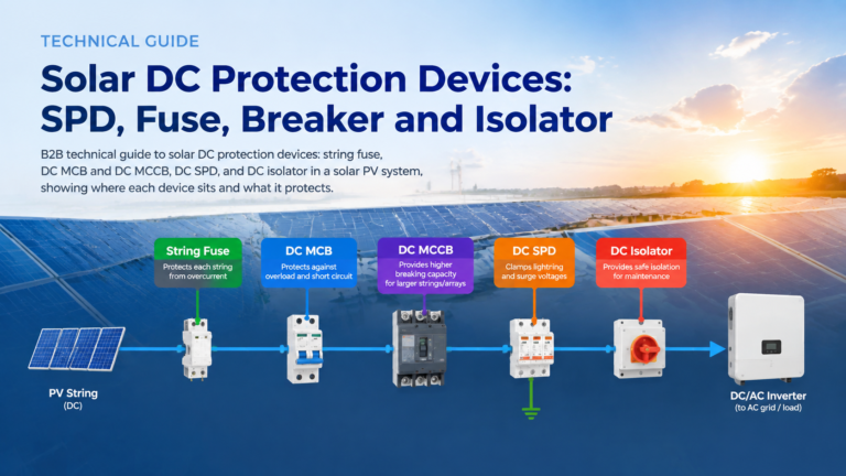
Solar DC protection is a chain, not a purchase. In one array you can have a reverse current from nine healthy strings into one faulted string, a lightning-induced impulse arriving on the same conductors, and a maintenance team that needs to work on the inverter DC input — three problems that share a cable and […]