Why a Solar Combiner Box Needs Both a DC MCB and DC SPD
Publié le : Auteur : Rachel
A solar combiner box asks two completely different questions of its protection. Will this circuit survive a fault? And will this circuit survive a surge? A Disjoncteur à courant continu answers the first question. A DC SPD answers the second. The two devices are often discussed together — and just as often confused — because both sit on the same DC busbar, both are DIN-rail mounted, and both are loosely described on site as “the protection”. They are not interchangeable. Neither can be replaced by the other, however carefully it is sized.
This article is about protection coordination — the DC MCB and DC SPD in combiner box pairing. It covers the division of labour between overcurrent protection and transient overvoltage protection, what each device protects and what it cannot, why substitution fails, how the two are coordinated on the same bus including the SPD’s backup protection requirement, what is left exposed if either one is omitted, how the pairing changes between 1000 V DC and 1500 V DC systems, and the selection principles that keep the pair working as a pair.
It deliberately does not re-derive device selection. The DC MCB guide, the DC SPD selection guide and the PV fuse sizing guide each own their own method, and this article links to them at the point where you need them.
Safety Before Anything Else
Everything below is a design discussion about equipment you will eventually open. A combiner box sits on a live DC system, and DC behaves differently from AC.
PV arrays are live in daylight. There is no off switch on a module. An isolated string still carries full open-circuit voltage, and a combiner box on a working array is never fully de-energised just because the inverter is off.
Isolate, verify dead, then work. Prove your tester on a known live source both before and after the test, and treat an unexpected reading as real.
Do not work on energised PV strings. Insulation-resistance and continuity checks require the strings isolated at both ends.
Wear arc-rated PPE and insulated gloves. A DC arc does not self-extinguish at a current zero, so a DC-side fault is harder to clear than the equivalent AC fault — which is precisely why the overcurrent device matters.
Two Failure Modes That Look Nothing Alike
The reason a combiner box needs both devices is that the two threats it faces have almost nothing in common.
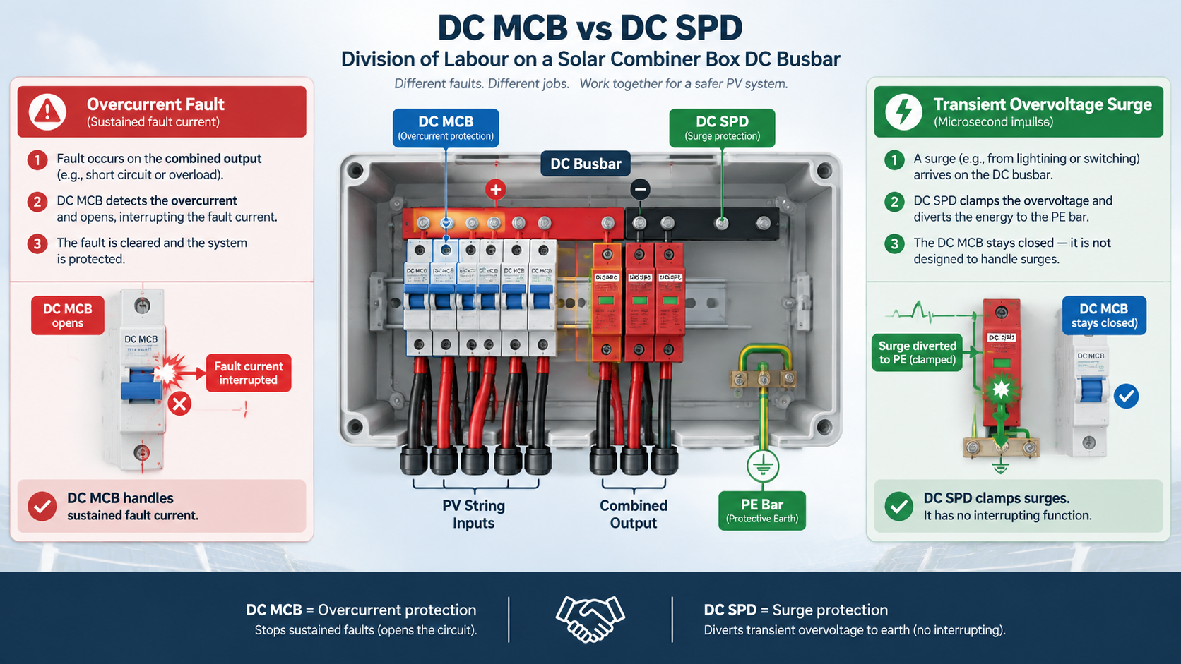
Overcurrent is a sustained or near-instantaneous flow of current above the circuit’s design value. It happens because a fault path exists: an insulation failure in a string, a short circuit in a connector, a module failure, or a reverse/back-feed current from healthy strings into a faulted one. It rises from the system’s own voltage source, it persists until something opens the circuit, and its energy is delivered over milliseconds to seconds. It must be interrupted.
Transient overvoltage is a brief, very high-voltage impulse — typically from nearby lightning, switching, or a utility-side event — superimposed on a circuit that is otherwise working perfectly normally. It lasts microseconds, it does not necessarily involve any extra current flow in the load, and it does not trip anything. It must be diverted, and it attacks insulation, semiconductors and the devices themselves rather than the load.
A device that interrupts current is useless against an impulse; a device that diverts an impulse is useless against a sustained fault. That single sentence is why both devices exist. The rest of this article is the practical consequence of it.
Two jobs, two devices: the breaker interrupts a sustained overcurrent, the SPD diverts a microsecond impulse it cannot interrupt.
What the DC MCB Protects — and What It Cannot Do
The DC MCB is the overcurrent and switching device on the combined DC circuit. Inside a combiner box its usual jobs are:
Clear a short circuit or a severe overload on the combined output and on the circuit downstream of it, before conductor insulation, connectors or the busbar are damaged.
Provide a rated, re-settable disconnection point so the combined string output can be isolated from the inverter DC input for maintenance — instead of the whole array being worked on live.
Serve as the device a fuse can coordinate with. A fault on one string is then cleared by that string’s fuse while the combined circuit stays energised and the remaining strings keep producing. How those two curves are matched is the fuse-versus-breaker coordination question, not the subject here.
What a DC MCB cannot do is just as important. It has a rated impulse withstand voltage, and a lightning-induced surge can exceed that by an order of magnitude. The breaker does not see a surge as an overcurrent: it does not open, it does not clamp the voltage, and it does not absorb the energy. The impulse simply passes through it, arrives at whatever is downstream, and is dissipated wherever the weakest insulation happens to be — often inside the inverter’s DC input stage, which is far more expensive than the breaker.
This is also why an AC-rated breaker is not a substitute on the DC bus in the first place. DC rating, construction, arc-extinction behaviour and the pole arrangement used to reach a given DC voltage are all device and manufacturer specifics that must be read from the datasheet. If you are selecting the breaker itself, work through this DC MCB guide for solar PV and EV applications, which covers construction and selection in full.
What the DC SPD Protects — and What It Cannot Do
The DC SPD is a voltage-limiting, energy-diverting device. Mounted on the DC bus with a short, direct connection to the protective earth bar, it presents a very high impedance at normal system voltage and a very low impedance once the voltage rises above its threshold. When an impulse arrives, the SPD conducts the surge energy to earth and clamps the residual voltage seen by the equipment to a level defined by its voltage protection level, Up.
That is the whole of its protective function, and it is a function nothing else in the box performs:
It limits the impulse voltage that reaches the inverter DC input, the string conductors and the busbar insulation.
It protects itself and the circuit after a surge — but only to the extent that the surge was within its declared capability. An SPD is a sacrificial component, and its service life is consumed by surge events.
It does not interrupt. An SPD cannot clear a short circuit, cannot clear an overload, and cannot be used as an isolation point. If a string faults while the inverter is running, the SPD does nothing at all about it.
There is a second limitation that catches people out, and it is the direct link between the two devices. An SPD’s end of life is not always an open circuit. A degraded metal-oxide varistor, or a gas discharge tube following a sustained temporary overvoltage, can fail to a low-impedance state. At that point the SPD looks like a fault on the DC bus. It has become an overcurrent event, and something must interrupt it before the SPD’s own housing is destroyed. That “something” is the SPD’s backup protection — and it is why the pairing in a combiner box is a genuine coordination problem rather than two independent purchases.
Selection of the SPD itself is covered in the dedicated DC SPD selection guide: Type 2 DC surge suppressor selection for solar, BESS and DC panels. This article assumes that selection step is done and concentrates on how the chosen SPD and the chosen breaker sit together.
Why One Cannot Substitute for the Other
Attempts to use a single device for both jobs usually rest on one of three misunderstandings.
“The breaker will trip and protect everything.” It will trip on overcurrent. A surge is not an overcurrent in the sense the breaker detects; it is a microsecond-scale voltage event. The breaker’s contacts stay closed and the impulse passes straight through. The equipment downstream still sees the full impulse.
“The SPD will divert anything dangerous.” The SPD diverts impulse energy. Apply a sustained overcurrent to it — a faulted string, a shorted output, an SPD that has failed to low impedance — and it will conduct until it destroys itself, because it has no interrupting element. An SPD without backup protection is a component that converts a surge problem into a fire risk.
“One device covers both because it is rated for both.” A device can carry a DC voltage rating and a rated impulse withstand voltage without being a surge protective device. Impulse withstand is the level the device will survive, not the level it will limit for the rest of the installation. Only an SPD has a declared voltage protection level and a declared surge current capability.
The cleanest way to see the split is to look at the two devices side by side.
Question
Disjoncteur à courant continu
DC SPD
What is it for?
Overcurrent: overload and short circuit
Transient overvoltage: impulse and switching surges
What does it do?
Opens the circuit and interrupts current
Conducts the impulse to earth and clamps the residual voltage
Typical event duration it responds to
Milliseconds to seconds (instantaneous element for short circuits)
Microseconds
Does it protect the inverter DC input from lightning-induced impulses?
No — it does not limit voltage
Yes — this is its purpose
Does it clear a faulted string or a shorted output?
Yes, within its rating and coordination
No — it has no interrupting function
Does it provide a maintenance isolation point?
Yes, where it is rated as a disconnector for the duty
Non
Does it need backup protection of its own?
No — it is the protection
Yes — a maximum overcurrent protective device declared for the SPD
What marks end of life?
It operates; it can be re-closed after the fault is found and cleared
A status indicator and cumulative surge exposure; replacement, not reset
How the Two Devices Coordinate Inside the Box
Having both devices fitted is not the same as having them coordinated. Three things must be true.
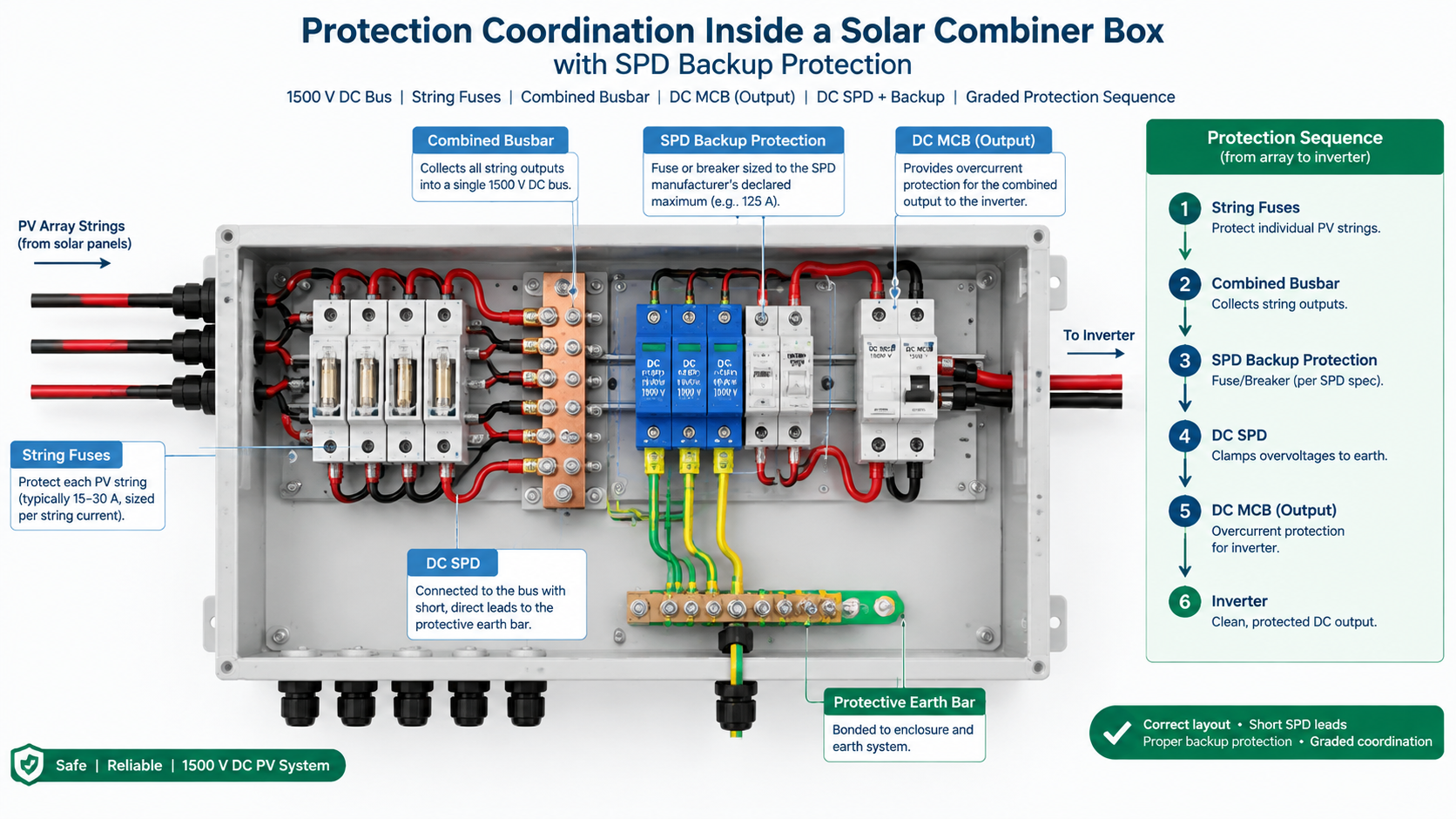
1. They sit at the right points on the DC bus. The SPD belongs on the DC bus it is protecting, close to the conductors and the equipment it shields, with its connecting leads kept as short and as straight as practicable — long, looped leads add inductance and raise the voltage that actually reaches the equipment. The mechanical layout of the box, the busbar, the earth bar and the sequence of devices is what makes this possible or impossible, and it is set out in the combiner box wiring diagram. Get the layout right on paper before you order hardware; a correctly selected SPD installed with long leads is a compromised SPD.
2. The SPD has its own backup protection, correctly sized. This is the coordination requirement most often missed. Every SPD is declared with a maximum rating of overcurrent protective device that may be used ahead of it — a value the manufacturer publishes precisely because the SPD may fail to a low-impedance state and must then be cleared. The backup device may be a dedicated fuse, or it may be the DC MCB already in the box if that breaker’s rating and characteristic fall within what the SPD permits. It must not be larger than the declared maximum, and it must not be so small that normal inrush or surge currents operate it. The logic of choosing between the two options is covered in SPD backup: fuse or circuit breaker.
3. The type and configuration match the DC system. A DC combiner bus is not an AC distribution board, and the SPD arrangement — including how the connections are made and how many poles are used — must be the type intended for that DC application. The practical question of which configuration is used on a solar DC distribution board is answered in which type of SPD is used in a solar DCDB.
Two further points belong here because they are the difference between a compliant pair and a dangerous one. First, do not reduce the SPD’s backup protection rating to stop it operating during a surge or inrush event; if the backup device operates in normal service, the selection is wrong and must be re-checked, not downgraded. Second, do not treat the MCB as the SPD’s backup device unless the manufacturer’s declared maximum allows it — the number in the datasheet governs, not the fact that a breaker happens to be upstream.
Coordination on the bus: the SPD sits on the DC bus with short leads to the earth bar, backed by the overcurrent device declared for it.
What Happens If You Remove One
This is the comparison that decides whether the two devices are optional. In both columns the remaining device is correctly sized and correctly installed; the only change is that one device is gone.
Configuration
What still works
What is now unprotected
First realistic failure
DC SPD removed, DC MCB retained
Short circuits and overloads are still cleared; isolation is still available
The whole DC bus against transient overvoltage — string conductors, busbar insulation, and the inverter DC input
A nearby lightning event or a switching surge damages the inverter DC input stage, with no evidence in the box that anything happened
DC MCB removed, DC SPD retained
Impulse overvoltages are still limited and diverted to earth
Every overcurrent condition on the combined output — shorts, overloads, and any SPD that has degraded to low impedance
A faulted output or a failed SPD draws sustained current with nothing to interrupt it, leading to conductor damage and a fire risk inside the enclosure
Both fitted, SPD backup protection missing or oversized
Overcurrent protection and surge diversion both appear to be in place
The SPD’s own failure mode — the case it was designed to have cleared
The SPD degrades to low impedance and is destroyed rather than disconnected, damaging the enclosure around it
Both fitted, SPD fitted with long, looped leads
The circuit is nominally protected; the SPD does conduct
The clamping performance the SPD was selected for
Equipment damage in exactly the event the SPD was bought for, with an SPD that still shows a healthy indicator
Nothing in the table is a device-quality problem. Every row is a coordination problem, and every one of them is present on real installations.
1000 V DC Versus 1500 V DC: How the Pairing Changes
The two devices scale differently with system voltage, and that difference is where most 1500 V design errors start.
The DC MCB’s voltage rating is a hard limit, not a margin. A device rated for 1000 V DC must not be used on a 1500 V DC bus. Higher DC voltage ratings are reached through construction: greater contact separation and arc-control design, and in some product families a defined multiple-pole arrangement in series. That arrangement is specified by the manufacturer for the device in question — it is not a rule you can apply yourself to a 1000 V part. Read the DC voltage rating and the permitted pole configuration from the datasheet, and confirm the device is rated for the array’s maximum system voltage at the lowest expected temperature, which is where open-circuit voltage is highest.
The DC SPD has to clear a higher continuous voltage. The relevant parameter is the maximum continuous operating voltage, Uc, which must be at or above the highest sustained voltage the DC bus can present, with the applicable margin for the standard and the system. On a 1000 V DC array that generally leads to a 1000 V or 1200 V class device; on a 1500 V DC array it leads to a 1500 V class device. Choosing an SPD whose Uc is too low for the bus is not a small error — it puts the device into continuous conduction, which is a classic route to premature failure and to a temporary overvoltage event the SPD cannot survive. The voltage-class decision is set out in 1000 V versus 1500 V DC SPD, including how the class interacts with the earthing arrangement and the location of the SPD in the system.
Raising the system voltage changes the coordination, not just the labels. A higher operating voltage across the same installation means the residual voltage the equipment sees in a surge event is a larger fraction of the insulation’s capability, so the voltage protection level matters more, not less. It also means that if the SPD’s backup protection is selected on the assumption of a 1000 V circuit, both the interrupting capability and the voltage rating of that backup device may be inadequate on a 1500 V bus. When you move a combiner box design from 1000 V to 1500 V, revisit the MCB rating, the SPD voltage class, and the SPD’s backup protection together. Never change one of the three on its own.
Selection Principles That Keep the Pair Intact
These are principles, not a selection method. Each points to the guide that owns the detail.
Size the two devices for two different events. The MCB is sized against the circuit’s prospective fault current, its continuous current and its coordination with the string fuses. The SPD is selected against the system’s voltage class, the surge environment at the site, and the voltage protection level the downstream equipment needs. They are not alternatives and they are not a trade-off — spending more on one does not reduce the requirement for the other.
Confirm the SPD’s declared maximum backup protection and make the box satisfy it. Decide whether that is a dedicated fuse or the existing DC MCB, and record the decision. This is the coordination requirement that most often goes unverified.
Match both devices to the actual maximum system voltage. 1000 V DC hardware on a 1500 V DC bus is a rating violation for both the breaker and the SPD, and the failure is silent until it is not.
Design the layout before ordering. Short, direct SPD leads to the earth bar; the SPD on the bus it protects; the breaker where it can be operated and where the fault current path is sane. A layout that forces long SPD leads wastes the SPD’s rating.
Plan the inspection routine around both devices. The breaker is checked for correct operation and for evidence of thermal stress; the SPD is checked for its status indication and replaced when it reaches end of life, because an SPD that has done its job correctly is not a warranty claim — it is a device that needs replacing.
Common Mistakes
Treating the DC MCB as surge protection. The most expensive version of this mistake is discovered only after the inverter is damaged.
Fitting an SPD with no backup protection on the assumption that the upstream breaker will handle it, without checking the SPD’s declared maximum.
Reducing the backup protection rating to stop it operating. If it operates in normal service, the selection is wrong; fix the selection rather than the rating.
Installing the SPD with long, looped connecting leads. The device is fine; the installation defeats it.
Keeping a 1000 V DC breaker or SPD in a design that has been upgraded to 1500 V DC. This usually happens because only the array and inverter were re-specified.
Replacing a cleared string fuse or re-closing a tripped breaker without diagnosing the fault. A protective device operating is a symptom. Re-energising repeatedly without finding the cause is how a small insulation fault becomes an enclosure fire.
Frequently Asked Questions
Can a DC MCB replace a DC SPD in a combiner box?
No. A DC MCB interrupts overcurrent; it does not limit transient overvoltage. A surge is a microsecond-scale voltage impulse during which the breaker stays closed and the impulse passes straight through to the inverter DC input. The two devices protect against different events and cannot substitute for each other.
Does a DC SPD need its own fuse or breaker inside the combiner box?
It needs backup protection whose rating is at or below the maximum overcurrent protective device declared by the SPD manufacturer. That backup device may be a dedicated fuse, or it may be the DC MCB already in the box, provided that breaker’s rating and characteristic fall within what the manufacturer permits. If neither satisfies the declared maximum, add a correctly rated dedicated device.
Should the SPD be fitted before or after the main DC breaker?
The SPD must be connected to the DC bus it is protecting, with short, direct leads to the protective earth bar. Whether that point is on one side or the other of the output breaker depends on the enclosure layout and on what the SPD is intended to shield, and it should be decided with the box’s wiring arrangement in front of you rather than by rule of thumb.
Do I need both devices on a 1000 V DC system, or only on 1500 V DC systems?
Both devices are required whatever the voltage class. The need for overcurrent protection and the need for transient overvoltage protection are independent of the system voltage — a 1000 V array is just as vulnerable to a lightning-induced impulse as a 1500 V one. What changes with the voltage class is the rating of each device, not whether you need it.
What size DC MCB should be paired with a DC SPD?
They are selected for different duties, so there is no single pairing rule. The breaker is selected against the circuit’s continuous current, prospective fault current, and coordination with the string fuses; the SPD is selected against the system’s voltage class, surge environment and required voltage protection level. The only direct constraint between them is that the breaker must be an acceptable backup device for the SPD, which means falling within the SPD manufacturer’s declared maximum. If it does not, a separate backup device is needed.
Where to Go From Here
In a combiner box, the DC MCB and the DC SPD are not two options for one job. They are two devices for two different jobs on the same busbar, and the installation is only as good as the weaker of the two links — including the backup protection that connects them. Confirm both ratings against the actual maximum system voltage, confirm the SPD’s declared backup protection is satisfied by what is in the box, and design the layout so the SPD’s leads stay short.
If you are specifying a combiner box for a project and want the protection content reviewed against your array’s voltage class and string configuration, review the combiner box range and send us your system parameters — the arrangement of the overcurrent and overvoltage devices is the part of the specification that is worth getting right on paper first.
Ask when should an SPD be replaced and most answers stop at the status window. That is one input, and on its own a weak one: it shows that a device has reached end of life, never that a device is still fit for service. An SPD can be electrically exhausted while the window still […]
“Combiner box vs junction box” is one of the most common points of confusion in PV design, and it is not a cosmetic one. The two enclosures look similar on a wall, are both described loosely as “the box where the strings are terminated”, and are not interchangeable. A junction box is a passive termination […]
Solar combiner box maintenance is the cheapest protection a PV asset can buy. A short scheduled inspection finds a hardening door gasket, a slack terminal or a saturated desiccant while they are still minor defects; the same three found two years later are an earth fault, a discoloured busbar and a lost production week. This […]