Cómo instalar una caja combinadora solar: guía paso a paso
Publicado: Autor: Rachel
Most problems found inside a PV combiner box a year after handover are not caused by the protection devices themselves. They come from how the enclosure was mounted, how the cables were glanded, how the terminals were tightened, and what was never verified before the strings were energised. This guide covers how to install a solar combiner box in the right order: position, mounting, IP integrity, earthing and labelling, then commissioning with recorded test results.
This article covers physical installation and commissioning only. The internal wiring logic — how strings are paralleled onto the busbar, and where each fuse, breaker and SPD sits in the circuit — is covered in full in our Esquema de cableado de la caja de conexión solar guide. Read that first if you are still deciding what goes inside the box. Read this one when the box is on site.
Safety Rules Before Any Work Starts
A DC arc does not self-extinguish at a current zero, so a fault that clears itself on an AC circuit will sustain on a PV string. Treat the following as mandatory.
PV arrays are live in daylight. There is no “off” switch on a module, and a disconnected string is still live.
Isolate, verify dead, then work. Open the string fuses or DC isolator, confirm the open position, and prove the conductors dead with a tester proven on a known live source before and after the test.
Do not work on energised PV strings. Insulation-resistance and continuity tests require the strings isolated from the combiner and the inverter.
Wear PPE — arc-rated clothing, insulated gloves and a face shield for anything involving energised DC terminals.
Respect dual supply. A combiner box can be fed from the array side y the inverter or battery side. Isolate and verify both, and label it as dual-supply.
Step 1 — Choose and Orient the Mounting Position
The first decisions in how to install a solar combiner box are made before any tool comes out, because position decides whether the box survives twenty years on site.
Shade and solar gain. Prefer a position out of continuous direct sun. Internal temperature rise shortens the life of fuses, SPD cartridges and gaskets and reduces the current-carrying capacity of everything inside.
Ambient temperature. Fuse and breaker ratings are typically established at a reference ambient, so read the manufacturer’s temperature-derating data rather than assuming the nameplate rating applies — a device correctly sized at 25 °C may be marginal at 55 °C.
Working space. Leave room for the door to open fully and for a technician to work with a torque wrench and a meter. Verify the local minimum working clearance before the rail goes up.
Cable runs and access. Keep array-side and inverter-side runs short and symmetrical to limit voltage drop (PV combiner box sizing), and avoid the lowest point of a roof or anything under a gutter outlet. A box that needs a harness to inspect will not be inspected.
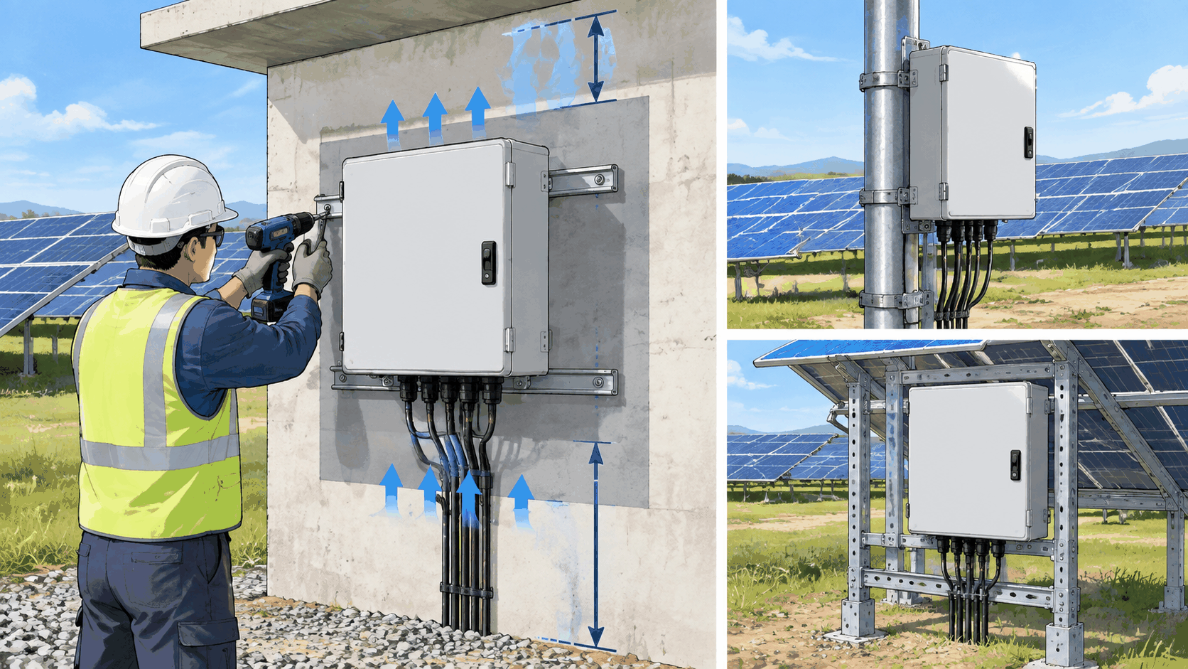
The enclosure must be fixed rigidly to a substrate that carries the load, including wind load on the door and box face. A box on four undersized plugs will work loose, distort its gasket and let water in.
Mounting method
Substrate to verify
Key checks before fixing
Wall mount
Masonry, concrete, or a structural steel frame
Substrate soundness; fixings rated for enclosure weight plus wind load; box level; door swing clear
Pole mount
Steel or concrete pole
Pole diameter matches the bracket range; two brackets used where specified; bracket bolts torqued; no rotation under wind
Rack / ground mount
PV mounting rail system or dedicated post
Rail is rigid and not a flexing module rail; bonding continuity across the structure; reinforcement at the fixings
Use stainless fixings in coastal, agricultural and high-humidity environments; galvanised fasteners corrode first, and a corroded fixing means a loose enclosure.
Mount plumb and level — a door that does not sit square on its gasket will leak, and no sealant will compensate for it.
Respect the manufacturer’s specified clearances, and do not mount onto a vibrating or wind-flexing structure. Never use the box or its mounting feet as a cable support or a step.
Step 3 — Ventilation, Shading and Condensation
A sealed box is not automatically a dry box. As the enclosure heats and cools it breathes through its gasket and glands, and moisture drawn in at night can condense on cool metal. At commissioning, look at the underside of the roof plate for droplets or corrosion trails.
Keep ventilation and pressure-equalisation elements unobstructed. Never tape over a breather or block a filtered vent.
Check any filter at commissioning and fit supplied desiccant as instructed — both are maintenance items, not permanent fixtures.
Do not drill extra holes “for airflow” in a sealed enclosure; that converts a rated box into an unrated one.
Step 4 — Conduit Routing and Cable Entry
Cable entry is where most water ingress problems begin, and it is almost always a workmanship issue rather than a product issue.
Enter from the bottom. Route conduit and cables into the underside so water runs away from the entry rather than along the cable. Top entry is the most common single cause of water in a combiner box.
Form a drip loop. Create a low point in each cable immediately before the gland so water sheds before it reaches the seal.
Match the gland to the cable. Select each gland for the measured cable outer diameter. Too large and it will not clamp or seal; too small and it will damage the cable.
Blank every unused entry. Any open knockout or missing plug is a direct path for water, dust and insects.
Support the cables and respect bend radii. Clamp runs so their weight is carried by the structure, not by the glands or terminals — strain relief at the entry is mandatory. Sharp bends stress insulation and are a hidden source of insulation-resistance failures. Bond metal conduit and tray, and verify continuity rather than assuming it.
Step 5 — Protecting the IP Rating
An enclosure’s IP rating describes the box as it left the factory. On site it is only as good as the installation and the maintenance that follows. Confirm the test conditions in IEC 60529 rather than working from memory — the difference between jet and powerful jet, for example, matters in an exposed location.
Inspect the door gasket before closing. Check it is seated in its channel, continuous at the corners, and free of grit, paint or cable debris. One trapped particle creates a leak path.
Do the door hardware up properly, using all the latches or screws provided, tightening evenly without distorting a composite door. Do not seal the door with silicone or tape — it hides the problem, damages the gasket and makes the box unserviceable.
Torque glands to the gland manufacturer’s specification. Under-torqued glands leak; over-torqued glands crush the seal and also leak.
Do not drill the top or side faces. If an extra entry is unavoidable, drill the bottom and re-seal correctly. Repair coating damage with the correct touch-up product, because that is where corrosion starts.
Step 6 — Enclosure Earthing and Bonding
Earthing protects people when insulation fails, and it is also the return path that makes an SPD effective. A surge protective device with a long or poor earth connection will not perform as specified.
Connect the protective earth conductor to the dedicated earth stud or terminal provided. Do not use a mounting foot, gland body or hinge unless the manufacturer explicitly designates it.
Where the enclosure is metallic and the door carries devices, verify the door bonding provision is present and continuous, and fit a supplied bonding strap. Verify continuity through gland plates after final assembly.
Size the earthing conductor per the local code and project specification — verify the requirement rather than copying a previous job.
With the system isolated, test continuity from the enclosure earth point through to the earthing electrode system and record the result. Keep the earth connection short and direct, which matters most where an SPD is fitted.
Step 7 — String Identification and Labelling
Labelling done during installation takes minutes. Done later, it takes hours and is performed on a live array by someone who did not build it.
Label every string input at the terminal or fuse position with the array identifier used on the site drawing, and label the same string at its origin.
Mark polarity clearly on DC terminals and outgoing DC conductors, and fit the required warning labels: DC voltage present, shock hazard, dual supply, and maximum system voltage where required.
Use permanent, UV-resistant, weather-rated labels; handwritten tape and marker pen fade within one season outdoors.
Put a printed as-built wiring diagram inside the door, showing the string-to-terminal assignment as installed.
Step 8 — Termination and Torque Practice
Loose terminations are the most common cause of hot spots, voltage drop and nuisance failures in combiner boxes, and both under-torque and over-torque cause damage. Over-torque strips threads and cracks terminal bodies; under-torque leaves a high-resistance joint that heats under load and loosens further as it thermally cycles.
All torque values come from the manufacturer. There is no universal figure. The correct value for each terminal is published in the device datasheet, the enclosure manual or on the nameplate, and it differs between fuse holders, breaker terminals, busbar lugs and SPD connections. Never work from a remembered number or a value used on another product.
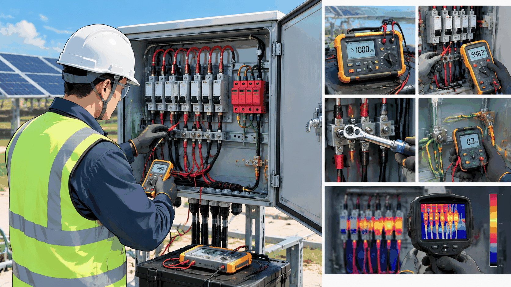
Use a calibrated torque screwdriver or torque wrench. A “good feel” is not a specification.
Strip to the length marked on the terminal or stated in the datasheet. Excess exposed conductor is a shock and short-circuit risk; too little prevents full contact.
Use ferrules on stranded conductors where the terminal type requires them, and any specified anti-oxidant compound on aluminium conductors.
Mark each terminal after torquing so a later check can confirm the joint has not moved, and record the tool identification and applied values. Plan a re-torque check after the first period of thermal cycling, as recommended by the manufacturer, because joints settle under load.
Step 9 — Pre-Energisation Checks
Pre-energisation checks are the part of how to install a solar combiner box that most often gets rushed. Complete this list with the strings still isolated from the combiner box and the inverter. Fixing an error now is cheap; finding it after energisation can mean a damaged inverter input stage.
Check
What you are confirming
Mechanical
Enclosure rigid and level; all fixings tight; door latches squarely; gasket seated; every unused entry blanked
Internal visual
No swarf, offcuts, tools or packaging inside; no damaged insulation; no moisture; desiccant fitted if specified
Protective devices
Correct device type and rating at each position, verified against the design and datasheet — including that PV string fuses are the correct class for DC PV duty, not a general-purpose fuse
Terminations
Every terminal torqued to the manufacturer’s value and marked; conductors fully seated; strain relief effective
Labelling
Every string identified at both ends; polarity marked; warning labels fitted; as-built diagram inside the door
Earthing
Earth conductor on the designated earth point; bonding continuity verified through doors, plates and glands; continuity to the earthing system measured
SPD status
Status indicator shows the healthy condition defined by the manufacturer
Step 10 — Commissioning Sequence
Work through the following in order, recording every result. IEC 62446-1 is the usual framework for PV commissioning tests and documentation; confirm the acceptance criteria in the current edition and in your EPC contract, because project specifications frequently set a stricter value than the published minimum.
Confirm isolation and prove dead. Both supplies isolated, open positions confirmed, conductors proved dead, and array conductors kept treated as live and covered where practical.
Repeat the visual walk-through with strings still disconnected, and photograph the completed interior before the door is closed.
Insulation-resistance test. With strings disconnected, test from each polarity to earth and, where applicable, between polarities, at the test voltage appropriate to the system voltage. Accept the result only if it meets the criteria in IEC 62446-1 and the project specification — read the current edition for the acceptance value rather than relying on a remembered figure. Test on dry modules: dew or recent rain can depress readings, so retest after a few hours of sun before condemning a string.
Polarity verification per string. Confirm positive to positive and negative to negative at each string input. A reversed string can destroy an inverter input stage, and this test takes seconds per string.
Open-circuit voltage per string. Measure Voc with the inverter disconnected and compare it against the temperature-corrected design value for the site’s lowest expected temperature — the figure on the approved design, not the module’s datasheet STC value.
Short-circuit current and string consistency. Where the specification requires it, measure Isc per string or use an I-V curve tracer, and compare strings against each other and against the expected value at the prevailing irradiance.
Fit and confirm the protective devices, then close the box and energise in the sequence defined by the manufacturer and the project method statement — normally combiner box first, then the inverter DC isolator, following the inverter manufacturer’s start-up procedure.
Verify at the inverter: the reported DC voltage should be consistent with your measurements, and the inverter should start within its expected delay.
Thermal scan under load. Once the array is producing, scan the interior, terminations, fuse holders, breakers and busbar with a thermal camera. Compare terminations against each other rather than against an absolute temperature: the joint running hotter than its neighbours is the one to re-torque. Record the scan images.
Handover Documentation
The installation is not finished until the records exist. Hand over insulation-resistance results with test voltage and ambient conditions; per-string polarity, open-circuit voltage and, where measured, short-circuit current; earth continuity results; the terminal torque record; thermal scan images with the load condition; photographs of the completed interior; the as-built string-to-terminal schedule; and the device types and ratings actually fitted, with the SPD status at handover.
Cngandian supplies combiner boxes and the DC protection devices that go inside them, and can provide the datasheets, torque data and installation documentation your project needs. To discuss a specific site, ponte en contacto con nosotros with the system voltage, string count and environment, or review the range on our caja de conexión solar página.
Common Installation Mistakes
Mistake
Consequence
Correct practice
Cables entering through the top face
Water tracks into the enclosure; corrosion and insulation failure
Bottom entry with a drip loop on every cable
Unused knockouts left open
Water, dust and insects inside a “sealed” box
Blank every unused entry with the correct plug and gasket
Gland not matched to the cable diameter
No seal and no strain relief; sheath damage
Select glands by measured cable outer diameter
Terminals tightened by feel
Hot spots, voltage drop, loosening under thermal cycling
Calibrated tool at the manufacturer’s published value, then marked and re-checked
Earth taken from a mounting foot or gland
Unreliable earth path; SPD unable to perform
Use the designated earth stud and verify continuity
Energising before polarity and insulation tests
Inverter input damage; a fault that could have been caught in minutes
Complete and record all pre-energisation tests first
No labelling or commissioning record
Fault-finding takes hours; warranty disputes become unwinnable
Permanent labels at both ends, an as-built diagram, and recorded test values
For the background on what the box does and why each internal component is there, start with what is a solar combiner box.
Preguntas frecuentes
Can a solar combiner box be installed in direct sunlight?
It can, provided the enclosure and every device inside are rated for the resulting internal temperature. Direct sun raises internal temperature well above ambient air temperature, which derates fuses and breakers and ages gaskets faster. Prefer a shaded position; if that is impossible, verify each device’s derating data against the expected internal temperature, not the site air temperature.
What clearances do I need around a combiner box?
The manufacturer’s installation manual specifies minimum clearance on each face, and local codes specify the working space in front of the enclosure. Both apply. Do not reduce either — the manufacturer’s clearance protects airflow and the gasket, and the code clearance protects the person who will service it.
Do I need to test insulation resistance before energising a new combiner box?
Yes. It is the standard way to detect a pinched cable, damaged connector or moisture ingress before it becomes a ground fault on a live system. Perform it with strings isolated, on dry modules, at the test voltage appropriate to the system, and record the result.
Can I leave a spare cable entry open for future strings?
Not open. Fit a proper blanking plug and gasket now, and remove it only when the new cable is glanded correctly. An open knockout defeats the enclosure’s IP rating immediately, and outdoors it will cause a corrosion and earth-fault problem long before the spare string is used.
What should be recorded at combiner box handover?
Insulation-resistance results with test voltage and ambient conditions, per-string polarity and open-circuit voltage, earth continuity results, the terminal torque record, thermal scan images with the load condition, photographs of the completed interior, the as-built string-to-terminal schedule, and the device types and ratings as fitted.
Compara las cajas de conexión fotovoltaicas fabricadas en acero con recubrimiento en polvo, acero inoxidable, aluminio, ABS/PC y GRP/poliéster en cuanto a corrosión, envejecimiento por rayos UV, disipación del calor, peso, fijación, índice de protección (IP) y coste, utilizando una matriz de selección basada en el entorno.
Por qué una caja combinadora solar necesita tanto un MCB de CC como un SPD de CC: la división de funciones entre la protección contra sobrecorriente y la protección contra sobretensiones transitorias; por qué ninguno de los dispositivos puede sustituir al otro; cómo se coordinan en el bus de CC, incluyendo el requisito de protección de respaldo del SPD; y cómo cambia esta combinación entre sistemas de 1000 V CC y 1500 V CC.
“Combiner box vs junction box” is one of the most common points of confusion in PV design, and it is not a cosmetic one. The two enclosures look similar on a wall, are both described loosely as “the box where the strings are terminated”, and are not interchangeable. A junction box is a passive termination […]