Solar DC Protection Devices: SPD, Fuse, Breaker and Isolator
Publicado: Autor: Rachel
Solar DC protection is a chain, not a purchase. In one array you can have a reverse current from nine healthy strings into one faulted string, a lightning-induced impulse arriving on the same conductors, and a maintenance team that needs to work on the inverter DC input — three problems that share a cable and nothing else. No single device answers more than one of them. So when you specify solar DC protection devices, the useful question is not “which device is best” but “which device belongs at this position, and what is it deliberately not doing”.
This article maps the whole DC protection chain — string fuse, MCB de corriente continua and DC MCCB, DC SPD, and the DC isolator or switch-disconnector — from the array through the combiner box, the inverter DC input, the battery or BESS, and the DC distribution board. It shows where each device sits, which failure mode it is there to handle, what it cannot do for you, and how the devices in the chain have to coordinate with each other. Device selection itself is owned by the dedicated guides, which are linked at each position rather than re-derived here.
One boundary note before we start. There is a separate, narrower article on the DC MCB and DC SPD pairing inside a combiner box. This article is the system-level map: the full chain, including the isolation devices, and the interfaces between the combiner box, the inverter, the battery and the DC distribution board.
Safety first, because the DC side behaves differently
PV arrays are live in daylight. There is no switch on a module. Opening a string isolator leaves the array side of that isolator at full open-circuit voltage.
Isolate, verify dead, then work. Prove your tester on a known source before and after the test. Treat an unexpected reading as real.
Do not work on energised PV strings. Insulation resistance, continuity and polarity checks all require the string isolated at both ends.
Wear arc-rated PPE and insulated gloves. A DC arc has no natural current zero to help it extinguish, so DC interruption is harder than the equivalent AC duty — which is exactly why every device in this chain must be DC-rated for the duty it performs.
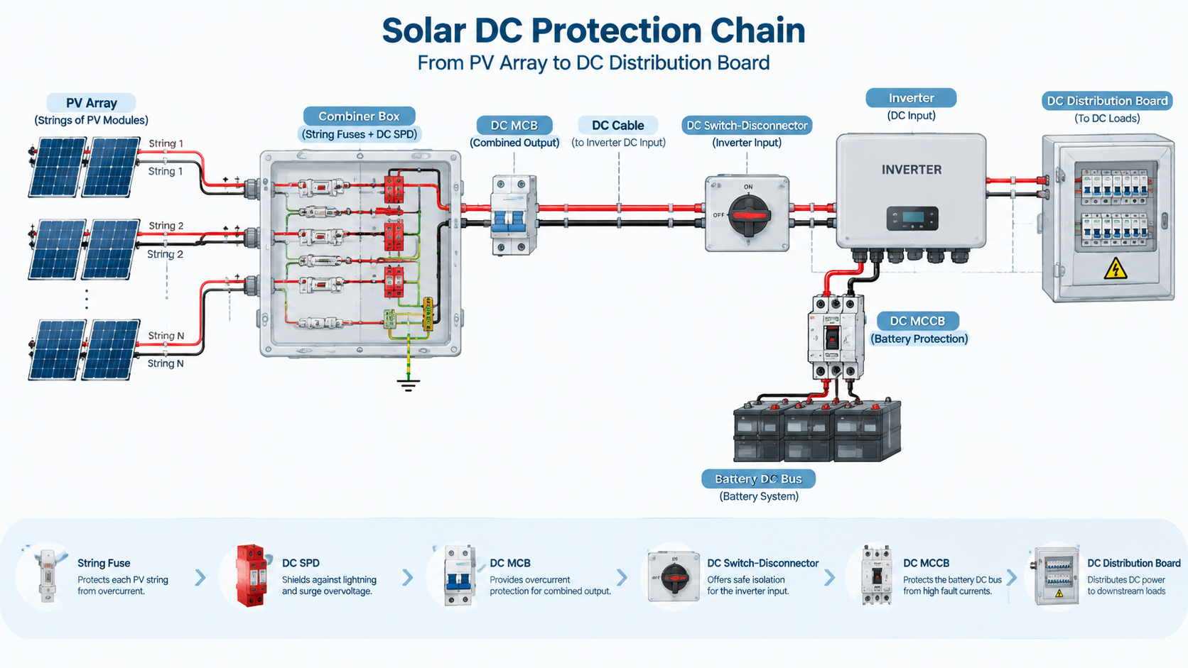
The DC protection chain: array to DC distribution
Think of the system as five zones, each with its own protection question and its own answer.
Array and string level. The concern is a faulted string being fed backwards by the healthy strings paralleled with it, plus the risk of overloading a string cable. The answer is the string fuse.
Combiner box. Strings are paralleled onto a common bus and leave the box as one or more combined outputs. The concern shifts to overcurrent on the combined circuit, to surges arriving on long DC runs, and to having a point where the output can be worked on. The answers are the DC MCB on the output, the DC SPD on the bus, and an isolator or switch-disconnector.
Inverter DC input. The inverter’s DC input stage is the most expensive, least robust component in the chain and must not receive an impulse it was not designed for. The answer is an SPD close to the inverter, plus a DC switch-disconnector so the input can be isolated.
Battery / BESS DC bus. A battery is a source in both directions, with a high prospective fault current and a very low impedance, so the concern is short-circuit energy and switching duty rather than load current. The answers are a DC MCCB (or a fuse plus a switch-disconnector) and a DC SPD matched to the bus.
DC distribution. Once DC is distributed to loads — EV chargers, telecom equipment, DC panels, auxiliary supplies — each outgoing circuit needs its own overcurrent device, and each board needs surge protection and an isolation point.
Two properties of this chain decide most of the design. Current can flow in either direction in a PV or battery circuit, so a device that only protects against current flowing one way is half the story. And each zone has its own earthing and voltage reference, so a device rated for one position is not automatically valid at the next. Much of the engineering depth sits in how the devices are laid out on the combiner box bus, which is set out in the Esquema de cableado de la caja de conexión solar.
The DC protection chain: one protection question per zone, and a different device at each position to answer it.
Device map: what each device does, and what it does not
This is the table to keep in front of you when a project specification lists solar DC protection devices as a single line item.
Dispositivo
Primary function
Ubicación típica
What it does not do
String fuse (gPV)
Interrupts reverse / back-feed current from paralleled strings into a faulted string; protects the string cable against overcurrent from the array side
Combiner box, one per string, in the positive (and where required the negative) conductor
It cannot limit a surge, cannot provide isolation, and cannot protect the string conductor against the string’s own short-circuit current — a module’s Isc is never high enough to operate a correctly sized string fuse
MCB de corriente continua
Overcurrent protection (overload and short circuit) and a re-settable, rated disconnection point on the combined or sub-array DC circuit
Combiner box output, sub-array output, inverter DC input circuit, DC distribution outgoing ways
It does not limit transient overvoltage, it does not stop back-feed current into a faulted string, and it does not detect earth leakage
MCCB de CC
Overcurrent protection at higher continuous currents and fault levels, often with adjustable settings, on the DC main
DC main of a large combiner, battery / BESS DC bus, DC distribution incomer
Same limits as the DC MCB: no voltage limiting, no string back-feed protection, no isolation rating unless the device is declared for that duty
DC SPD
Diverts impulse energy (lightning-induced or switching) to earth and clamps the residual voltage seen by the equipment to its declared Up
Combiner box DC bus, inverter DC input, battery / BESS bus, DC distribution board
It cannot interrupt any current — not a short circuit, not an overload — and it cannot be used as an isolation point. Without correct backup protection it becomes an overcurrent event in its own right
DC isolator / switch-disconnector
Manually isolates a section for maintenance, and where rated for the duty, makes and breaks load current under normal operating conditions
Combiner box output, inverter DC input, string or sub-array level, battery rack, DC board incomer
It does not clear a fault current unless it is specifically declared for that duty, it never operates automatically, and it cannot de-energise the array side of itself
Read the last column twice. Almost every DC protection failure on site is a device being asked to do something in that column.
Which device covers which problem
The other way to see the chain is by failure mode. The matrix below shows where each solar DC protection device contributes and where it is simply not involved — useful when you are reviewing a bill of materials and trying to find the gap.
Problem
String fuse
DC MCB / MCCB
DC SPD
DC isolator
Reverse / back-feed current into a faulted string
Yes — this is its main job
Usually no
No
No
Overload on a combined DC circuit
No
Sí
No
No
Short circuit on the combined DC circuit or DC main
Only by coordination
Sí
No
No
Lightning-induced or switching impulse
No
No
Yes — this is its only job
No
Sustained temporary overvoltage above the system voltage
No
Partial, only if it results in overcurrent
No — it must survive it, not clear it
No
Isolation for maintenance work
No
Where the device is rated as a disconnector
No
Yes — this is its job
Remote or automatic operation
No
Depends on the device and accessory
No
No
Earth leakage / insulation fault detection
No
No
No
No — this needs a dedicated device
Nothing in the table is optional decoration. Each row is a distinct physical event, and the devices that answer them sit at different points on the chain.
The string fuse: back-feed protection, nothing else
A string fuse exists because of the parallel connection. If ten strings are paralleled and one develops a short circuit across part of its length, the other nine push current into the fault. The faulted string’s own modules cannot produce enough current to damage its cable; nine strings’ worth can. The fuse is selected for that reverse-current case, and it is a DC-rated gPV fuse because that class is rated for DC and its characteristic suits a PV source. The standard context — IEC 60269-6 and UL 248-19 — is worth naming in a specification, because a general-purpose fuse of the same physical size is a different product.
The sizing itself — how the rating relates to string Isc, temperature derating, and the module manufacturer’s maximum series fuse rating — is covered in gPV fuse selection for 1000 V and 1500 V strings. What matters here is the boundary: the string fuse protects the string cable against current coming from the other strings. It does not protect the inverter, it does not isolate anything, and it will not operate for a surge. Nor is a fuse holder an on/off device — pulling a fuse on a live string is not a recognised isolation method. If you need switching at string level, that is a switch-disconnector.
DC MCB and DC MCCB: overcurrent on the combined circuit
Once strings are paralleled, the current is far higher and the fault modes change. The DC MCB on the combined output does three jobs: it clears an overload or short circuit on that circuit and on what is downstream of it; it gives a re-settable disconnection point where someone will actually need one; and it is the device the string fuses coordinate with, so a fault on one string operates that string’s fuse and leaves the healthy strings producing.
A DC MCCB takes over the same job where continuous current and prospective fault current are larger than a modular breaker can handle — typically the DC main of a large combiner, a battery / BESS bus, or the incomer of a DC distribution board. Some MCCBs allow trip settings to be adjusted, which turns coordination from a fixed curve match into a setting exercise that has to be recorded and maintained.
What neither device does is limit a surge. A breaker has a rated impulse withstand voltage — a level it will survive — and that is not the same as a voltage protection level that limits what the downstream equipment sees. An impulse passes through a closed breaker and arrives at the inverter DC input stage unclamped. Construction and selection detail for the modular devices is in the DC MCB guide for solar PV and EV applications, and for the larger frame devices in the DC MCCB guide for solar and battery systems up to 1500 V. Both cover how a DC rating is achieved and what the datasheet must declare; do not assume a breaker that looks right is rated for your array’s DC voltage.
DC SPD: the only device that limits voltage
The DC SPD is the one device in the chain whose entire purpose is the impulse. Mounted on the DC bus with a short, direct connection to the protective earth bar, it is effectively an open circuit at normal system voltage and becomes a low-impedance path to earth when the voltage rises above its threshold. It conducts the impulse away and clamps what the equipment sees to its declared voltage protection level. For PV DC applications the relevant device family is defined by IEC 61643-31, and the type designation — Type 1 for a device intended to handle partial lightning current, Type 2 for a device intended for the surge environment downstream of that — comes from the position and the exposure at the site.
Two boundaries matter at system level. First, the SPD’s maximum continuous operating voltage, Uc, must be at or above the highest sustained voltage the DC bus can present, with the applicable margin. On a 1000 V DC array that leads to one voltage class; on 1500 V DC it leads to another, and the two are different device families rather than two settings on one product. That decision is set out in 1000 V versus 1500 V DC SPD.
Second, the SPD needs backup protection. An SPD at end of life does not always fail open. A degraded varistor, or a gas discharge tube after a sustained overvoltage, can fail to a low-impedance state, at which point the SPD is a fault on the DC bus and something must interrupt it before the enclosure around it is damaged. Every SPD is declared with a maximum rating of overcurrent protective device that may be used ahead of it, and the device in your design has to be at or below that value. The SPD selection detail — Iimp, In, Imax, Up and how they combine — is covered in Type 2 DC surge suppressor selection for solar, BESS and DC panels.
The DC isolator and switch-disconnector: the device most often left out
The isolator is where the chain is most often incomplete, and it is worth being precise about the terminology because the words are used loosely on site.
Un isolator is a device whose purpose is to establish a visible, reliable break so that work can proceed safely. It is not intended to make or break load current. A switch-disconnector does both: it isolates, and it is rated to make and break current under defined conditions. That rating is expressed as a utilisation category in IEC 60947-3 for DC switching duties, and the category has to match what the device will actually do in service. A switch-disconnector chosen for a duty it is not rated for is not an isolator with extra capability — it is a device being operated outside its declared ratings.
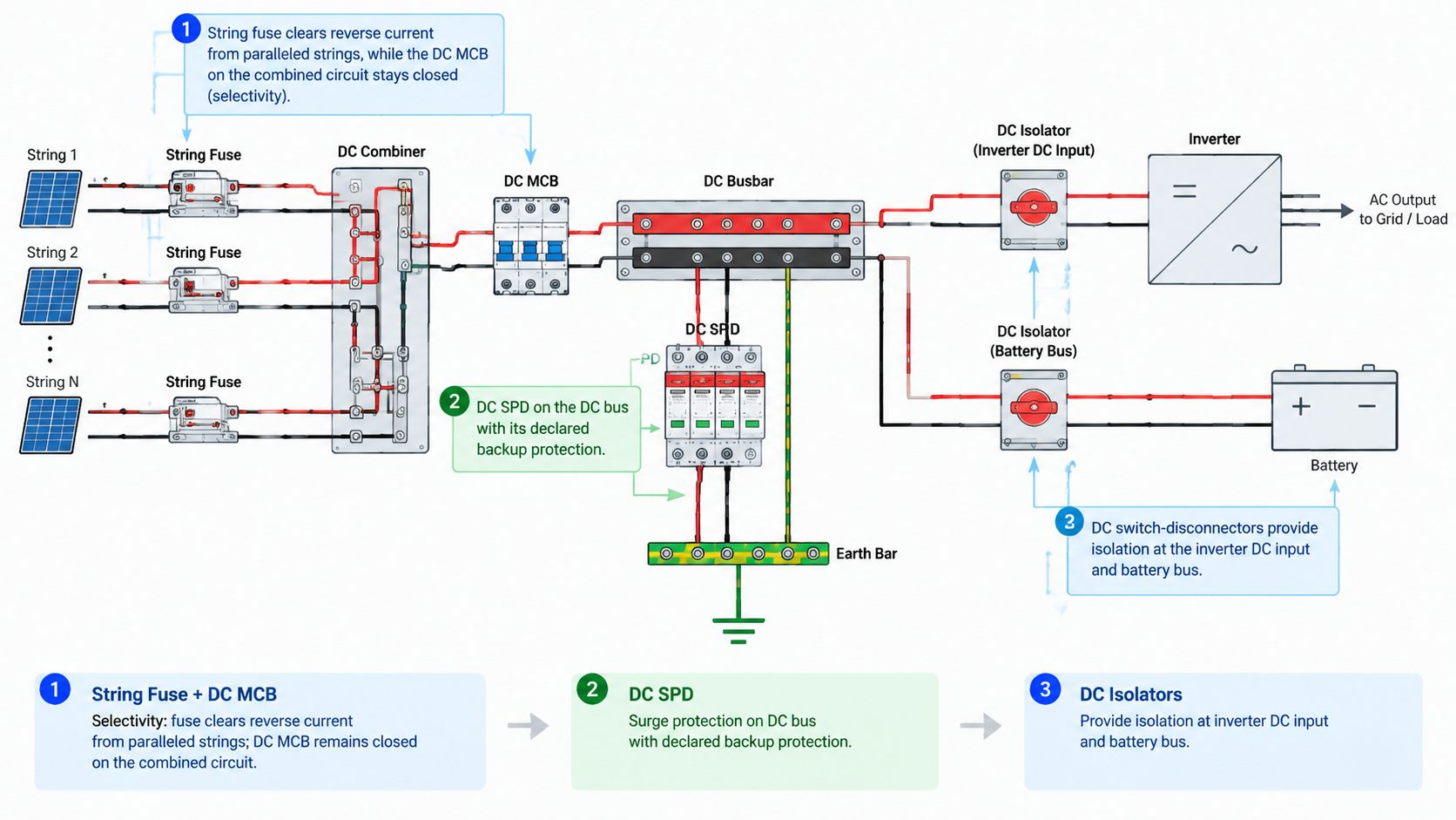
Where the isolator belongs depends on where people work. In practice that means the combiner box output or sub-array level, the inverter DC input, the battery rack, and the incomer of a DC distribution board. On a rooftop installation the DC isolator at the inverter input is also the device a firefighter may need to operate, which is a good reason to keep it accessible, correctly labelled and functional rather than theoretical.
Four limitations are worth stating plainly:
It does not clear faults. Unless a device is specifically declared for that duty, it must not be expected to interrupt a fault current. Using the isolator to “open a shorted circuit” is a way to destroy the switch and injure the operator, and it is not a substitute for the fuse or breaker upstream.
It cannot de-energise the array side of itself. Opening the inverter input isolator leaves the DC cable back to the combiner box live in daylight. Every isolation point has to be chosen with the source side of the circuit in mind, and the working procedure must prove dead at the point of work.
It never acts automatically. A protection scheme that depends on someone remembering to open a switch is not a protection scheme.
Its voltage and current ratings are DC ratings. Maximum system voltage, including open-circuit voltage at the lowest expected temperature, and the current it must make and break are the figures to verify — on the datasheet and on the nameplate.
An array with a correctly sized fuse, a correctly sized DC MCB and a correctly installed SPD but no isolation point at the inverter DC input is not protected for the work that will happen on it. It is only protected for the faults that might happen to it.
How the devices in the chain coordinate
Fitting all four device types is the easy part. Making them work as a chain takes four decisions.
1. The string fuse and the combined-circuit breaker must be selective. When one string faults, the string fuse must operate and the output breaker must stay closed, so that the fault is isolated and the rest of the array keeps producing. The two curves, and the I²t let-through of the fuse relative to the breaker’s response, are what determine whether that actually happens. Get it wrong in one direction and a single string fault takes the whole sub-array offline; get it wrong in the other and the fuse never operates at all. This is a design calculation, not a rule of thumb, and it has to be redone whenever either device changes.
2. Every overcurrent device has to be coordinated with the conductor and the equipment it protects. A fuse or breaker that is larger than the cable it sits on protects nothing except the enclosure from the outside in. On the DC side this also includes the equipment’s own DC input rating.
3. The SPD’s declared backup protection has to be satisfied by the design. The backup device may be a dedicated fuse or the DC breaker already on the bus, but only if its rating falls within the SPD manufacturer’s declared maximum. Verify this as a line item, not as an assumption.
4. The whole chain has to sit in one voltage class. If the array is 1500 V DC, then the string fuses, the breaker, the SPD, the isolator and the backup protection are all 1500 V DC devices. A mixed chain usually results from an upgrade where the modules and inverter were re-specified and the protection hardware was not.
Physical layout is part of coordination too. The SPD belongs on the bus it protects with leads kept as short and as straight as practicable, because long, looped leads add inductance and raise the voltage that actually arrives at the equipment — an SPD that is correctly selected but badly positioned still fails to protect. The busbar, the earth bar and the device sequence are a drawing problem before they are a purchasing problem.
Coordination across the chain: the string fuse protects the string, the breaker protects the combined circuit, and the SPD is backed by a device within its declared maximum.
Selection principles at each position
These are the questions to answer at each point in the chain. Each one points to the guide that owns the method.
Position
Dispositivo
First question to answer
What the datasheet must declare
Detail guide
String entry, inside the combiner box
gPV string fuse
What is the maximum reverse current this string can see from the other strings?
DC voltage rating, rated current, breaking capacity, gPV characteristic
Two constraints run across all six rows. Never choose a device by physical size or by what is already on the shelf, and never widen a protective setting or enlarge a fuse to stop nuisance operation. If a device operates in normal service, the selection is wrong and the fix belongs in the selection calculation — not in the rating.
The five mistakes that keep appearing
1. Omitting the isolator. The fuse, breaker and SPD get specified because they are protection, and the isolator is treated as an accessory. The consequence is a system that takes a fault well and cannot be maintained safely. Isolation is a design requirement at every point where work is planned, including the inverter DC input and the battery rack.
2. Using an AC-rated device on a DC circuit. An AC breaker or switch relies on the current passing through zero to help extinguish the arc; DC has no such moment, so the arc is sustained by the system voltage until it is stretched and cooled by the device’s own arc-control design. A device’s DC rating is a separate declared rating, not a derated version of its AC rating, and any derating factor for a specific device is manufacturer-specific and must be read from the datasheet. The same logic applies to fuses, switches and isolators. If it is a DC circuit, use a device with a DC rating for that voltage.
3. Expecting one device to do two jobs. The classic versions: a breaker standing in for surge protection, an SPD expected to clear a faulted string, a fuse holder used as a switch, an isolator expected to interrupt a fault. Each of these is a device being operated outside its function, and the failure is usually expensive and occasionally dangerous.
4. No coordination between fuse and breaker. Devices that are each correctly sized, but not selected as a pair, can fail to be selective. The result is a single string fault taking down a whole sub-array, or an output breaker that trips before the string fuse can operate, or a fuse that never operates because the upstream device is faster. Selectivity is a property of the pair, and it disappears the moment either device is changed without re-checking the other.
5. No SPD backup protection. An SPD without backup protection, or with a backup device above the declared maximum, protects the equipment from surges and then converts its own end of life into a sustained fault current with nothing to interrupt it. Confirm the declared maximum and confirm what is in the box satisfies it.
Frequently asked questions
What protection devices are needed on the DC side of a solar system?
At minimum: a DC-rated fuse or breaker for overcurrent protection on every circuit, a DC SPD for transient overvoltage protection at the points where surges enter, and a DC-rated isolator or switch-disconnector at every point where maintenance work will be carried out. Which combination sits at which position depends on the architecture — string level, combiner box, inverter input, battery bus and DC distribution each have a different set of risks.
Can a DC isolator be used to clear a fault?
Not unless the device is specifically declared for that duty. An isolator is there to establish a safe break for maintenance; a switch-disconnector is rated to make and break load current under defined conditions. Neither should be counted as the fault-clearing device on a circuit — that is the job of the fuse or breaker protecting that circuit.
Why does a PV system need both fuses and a DC breaker on the DC side?
They protect different things. The string fuse protects the string cable against reverse current from the other paralleled strings — a fault mode the combined-circuit breaker is not positioned to see. The DC breaker protects the combined circuit against overload and short circuit, and gives a re-settable disconnection point. Correctly coordinated, they also give selectivity, so one faulted string can be isolated without shutting the whole sub-array down.
Does a DC SPD protect the system from a faulted string?
No. An SPD diverts impulse energy to earth and limits voltage; it has no interrupting function at all. A faulted string produces a sustained overcurrent, which the string fuse or a coordinated upstream breaker has to clear. The two devices answer completely different events and cannot substitute for each other.
If the combiner box already has a breaker, do I still need an isolator at the inverter DC input?
They are not the same device in the same place. A breaker at the combiner box and a switch-disconnector at the inverter DC input sit at opposite ends of the DC run, and isolating one end does not necessarily make the other end safe to work on — particularly on a PV circuit, where the array side of any switch stays live in daylight. What you need at each point is decided by where people will work and what has to be proved dead before they start.
Can the same devices be used on a 1000 V and a 1500 V DC system?
No. The voltage class of the devices has to match the maximum system voltage of the array, and 1000 V and 1500 V DC families are different products with different declared ratings — not one product with two settings. If a design moves from 1000 V to 1500 V, revisit the fuses, the breaker, the SPD voltage class, the isolator and the SPD’s backup protection together rather than one at a time.
Where to go from here
Choosing solar DC protection devices is really four jobs, not one: keep reverse current off a faulted string, clear overcurrent on the combined circuit, divert impulses to earth, and make the system safe to work on. Every position in the chain gets one of each where it needs it, and the chain only works if the devices are coordinated as a set. Confirm that all of them are DC-rated for your array’s maximum voltage, confirm the SPD’s declared backup protection is satisfied by what is actually in the box, check the fuse and breaker are selective, and confirm there is an isolation point at every place someone will eventually put a hand.
Ask when should an SPD be replaced and most answers stop at the status window. That is one input, and on its own a weak one: it shows that a device has reached end of life, never that a device is still fit for service. An SPD can be electrically exhausted while the window still […]
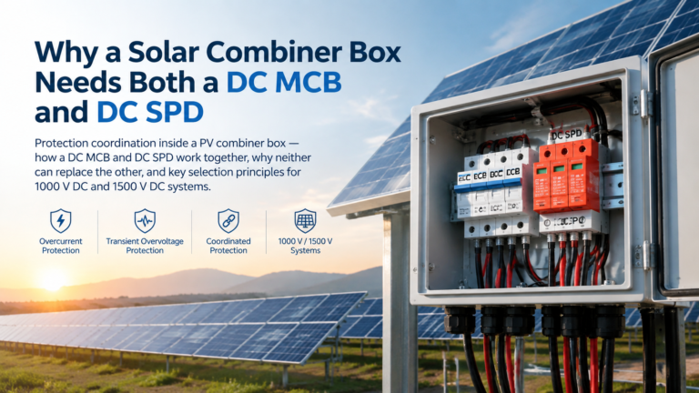
Why a solar combiner box needs both a DC MCB and a DC SPD: the division of labour between overcurrent and transient overvoltage protection, why neither device can substitute for the other, how they coordinate on the DC bus including the SPD backup protection requirement, and how the pairing changes between 1000 V DC and 1500 V DC systems.
“Combiner box vs junction box” is one of the most common points of confusion in PV design, and it is not a cosmetic one. The two enclosures look similar on a wall, are both described loosely as “the box where the strings are terminated”, and are not interchangeable. A junction box is a passive termination […]