Guía sobre las bases de fusibles de CA: tipos, valores nominales y selección
Publicado: Autor: Rachel
Si te dedicas a la fabricación o al mantenimiento de cuadros de distribución de baja tensión, montas fusibles constantemente. Pero el componente que sujeta cada fusible —el Base de fusible de CA — recibe mucha menos atención que el propio elemento fusible, a pesar de que de él depende la seguridad de todo el circuito. En esta guía se explica qué es una base de fusible de CA, cuáles son los tipos más habituales, los parámetros técnicos que hay que tener en cuenta y cómo elegir la más adecuada para un cuadro de control, un cuadro eléctrico o una caja de distribución.
¿Qué es una base de fusible de CA?
Un soporte de fusible de CA es el componente fijo de montaje y conexión que sujeta un elemento fusible en un circuito de corriente alterna. Mantiene el elemento fusible en su sitio, conduce la corriente de carga a través de sus terminales y permite sustituir rápidamente un fusible fundido sin necesidad de volver a cablear el circuito.
Sirve para separar las dos partes de un sistema de fusibles. El eslabón de fusible es el elemento protector sustituible: contiene el elemento fusible que interrumpe un fallo. El base del fusible es el material resistente que lo rodea: el cuerpo, los contactos y los terminales de tornillo que mantienen el elemento fusible conectado al cableado. El elemento fusible es un componente consumible; la base, por lo general, se instala una sola vez y permanece en servicio durante años.
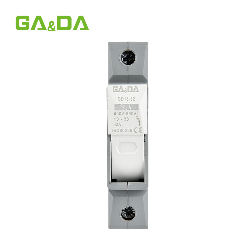
Una base de fusible industrial típica para corriente alterna, como la base de fusible para corriente alterna GA&DA, está homologada para circuitos de 690 V CA a 32 A o 63 A, admite eslabones de fusible NH/NH00 y de los elementos fusibles cilíndricos estándar de 10 x 38 mm, y se monta en un carril DIN de 35 mm o directamente en un panel. El cuerpo es de termoplástico ignífugo, cuenta con terminales de tornillo y tiene un rango de funcionamiento de -25 °C a +55 °C, y está fabricado según las normas IEC/EN.
¿Cómo funciona una base de fusible de CA?
En condiciones normales de funcionamiento, la corriente fluye desde el conductor de entrada, pasa por el terminal de la base, atraviesa el contacto y el elemento fusible, y sale por el segundo terminal. La base no interrumpe el paso de la corriente por sí misma; simplemente proporciona una vía de corriente estable y de baja resistencia, y mantiene el elemento fusible firmemente fijado en su sitio.
Cuando se produce una sobrecarga o un cortocircuito, el elemento fusible se funde y abre el circuito en ese punto. A continuación, la base sujeta el fusible fundido de forma segura en su posición, contiene el calor o la energía del arco eléctrico y permite que un electricista sustituya el elemento fusible por uno nuevo en cuestión de segundos.
Muchas bases modulares también incorporan funciones prácticas que van más allá de la sujeción del fusible:
Aislamiento: Las bases agrupadas 1P/2P/3P permiten aislar un circuito completo. Para aplicaciones en las que se necesite una función de conmutación completa, consulta qué es un seccionador de fusibles .
Indicación de fusible fundido: Las versiones con indicador muestran una señal visible o mediante LED cuando se ha disparado un fusible, lo que agiliza la localización de averías en cuadros de distribución con gran densidad de componentes.
Protección táctil: Las cubiertas y soportes de protección para los dedos permiten cambiar los fusibles sin exponerse a partes bajo tensión.
Tipos habituales de bases para fusibles de aire acondicionado
Las bases de fusibles de CA se clasifican principalmente según la familia de elementos fusibles que admiten y según su forma de montaje:
Tipo
Se aceptan eslabones de fusible
Valoraciones habituales
Ideal para
Base de fusible cilíndrica para carril DIN (tipo RT18)
10×38, 14×51, 22×58 mm
Hasta 125 A, 500/690 V CA
Cuadros de mando, cuadros de distribución, maquinaria
Base de fusible de cuchilla NH / NH00
Eslabones de fusible para cuchillas de tamaño NH000 a NH
De decenas a cientos de amperios
Aparatos de conmutación, transformadores y ramales de alimentación de motores
Base para fusibles de montaje en panel
5×20, 6×30, 10×38 mm
Valoraciones bajas o medias
Aparatos, instrumentación, acceso frontal al panel
Portafusibles para placas de circuito impreso
5 × 20, 6 × 30 mm
Baja intensidad de corriente
Placas de circuito impreso y equipos electrónicos
Las bases cilíndricas son la opción predeterminada en los armarios de control modernos, ya que se acoplan a un carril DIN de 35 mm y admiten cartuchos de fusibles estandarizados de las clases gG (uso general) o aM (circuito de motor). Las bases de tipo NH admiten corrientes más altas; por ejemplo, una base NH00 funciona con cartuchos de fusibles como el Elemento fusible de CA de la serie NT00 de GA&DA con una capacidad nominal de 160 A a 400 A. Cuando una base también deba conectar y bloquear un circuito, se utilizará una interruptor-seccionador con fusible combina ambas funciones en una sola unidad.
Características y especificaciones clave que hay que tener en cuenta
A fuse base is only as safe as its weakest rating. Before specifying one, check these parameters against your circuit:
Parámetro
Por qué es importante
Rated voltage (e.g. 500V or 690V AC)
Must equal or exceed the system voltage; the base must withstand the arc voltage when the fuse clears a fault
Rated current (e.g. 32A, 63A)
Must match or exceed the fuse link rating so the base does not overheat under normal load
Fuse link size and class
The fuse link must fit the contacts exactly — 10×38, 14×51, 22×58 mm, or NH blade sizes, in gG or aM class
Mounting type
DIN-rail and panel-mount bases suit different panel layouts
Terminal type and torque
Screw terminals must suit your conductor cross-section and be tightened to spec
Temperatura de funcionamiento
Confirm the base is rated for the ambient conditions inside the enclosure
Standards compliance
IEC/EN conformity (IEC 60269 family for fuse systems) indicates tested performance
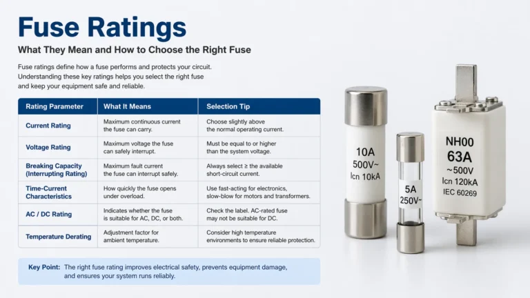
These values interact with the fuse link’s own limits. For a fuller explanation of current, voltage, and breaking capacity values, read the guide to fuse ratings explained.
How to Choose the Right AC Fuse Base
Selection becomes straightforward when you start from the fuse link and work outward:
Define the protection first. Choose the fuse link size, current rating, and class (gG for general distribution, aM for motor circuits) based on the load you are protecting.
Match the base to the fuse link. Confirm the base accepts that exact fuse link size and has a rated current at or above the fuse rating.
Check the voltage rating. A 690V AC base comfortably covers 400V and 230V systems; never use a base rated below your system voltage.
Pick the mounting style. DIN-rail bases speed up panel assembly; panel-mount bases give front access where space is tight.
Verify terminals and conductors. Make sure the screw terminals accept your cable cross-sections at the required torque.
Decide on indication. In panels with many circuits, indicator versions pay for themselves by cutting fault-finding time.
If you are still sizing the fuse itself, the walkthrough on how to select the right fuse rating covers the current and voltage calculations first.
AC Fuse Base vs DC Fuse Base
An AC fuse base cannot automatically be used in a DC circuit. Alternating current passes through zero many times per second, which helps the arc inside a blown fuse extinguish itself. Direct current has no zero crossing, so a DC fault arc can persist much longer and demands contacts, clearances, and arc chambers designed for it.
This is why manufacturers produce dedicated DC fuse bases with higher arc-quenching capability, commonly used in solar and battery systems. The underlying differences are the same ones covered in AC vs DC fuses — and if your project is a PV or battery installation, look at a purpose-built option such as the GDPV-32 direct current fuse base instead of an AC version.
Installation and Safety Practices
Most DIN-rail fuse bases install in a few minutes, but the details determine long-term reliability:
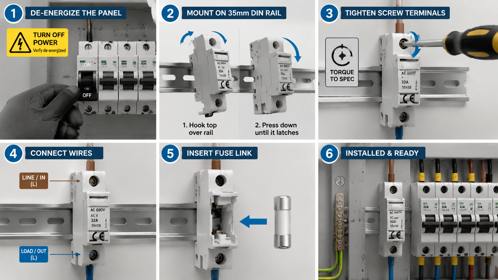
De-energize the panel and verify with a tester before touching any fuse base.
Hook the top of the base over the 35mm DIN rail first, then press the bottom until it latches.
Tighten screw terminals to the manufacturer’s torque value — undertightened terminals are a leading cause of localized overheating.
Seat the fuse link fully in the contacts; a partially seated fuse runs hot and can fail early.
Keep finger-safe covers in place so replacement can be done safely in live panels where regulations allow it.
Common Mistakes to Avoid
Substituting an AC base in a DC circuit. The arc may not clear, creating a fire and shock hazard.
Forcing a mismatched fuse link. A fuse link that does not match the contact geometry creates a high-resistance joint and heat damage.
Ignoring the base’s current rating. A 32A base carrying a 63A fuse link will overheat long before the fuse protects it.
Leaving terminals loose. Vibration and thermal cycling gradually loosen screws; recheck torque during scheduled maintenance.
Overlooking indication. Without an indicator, a single blown fuse in a three-phase circuit can leave a motor running on two phases.
Frequently Asked Questions
What does an AC fuse base do?
It holds a fuse link securely in an alternating-current circuit, provides the electrical connection between the fuse and the wiring, and allows the fuse to be replaced safely and quickly after it blows.
Can I use an AC fuse base in a DC circuit?
Not unless the base is explicitly rated for DC. DC arcs do not self-extinguish at a current zero, so the base must be designed with the arc-quenching capability and clearances required for DC service.
What fuse links fit an AC fuse base?
Each base accepts one family of fuse links — commonly 10×38, 14×51, or 22x58mm cylindrical links on DIN-rail bases, or NH/NH00 blade links on larger bases. The fuse link size, current rating, and class (gG or aM) must match what the base is built for.
How do I know which fuse base rating I need?
Start with the fuse link your circuit requires, then choose a base whose rated voltage and current are equal to or higher than the fuse link’s ratings, and confirm it accepts the same fuse link size and mounting arrangement.
DIN rail or panel mount — which should I choose?
DIN-rail bases are faster to install and reposition, which suits control panels and distribution boards that change over time. Panel-mount bases give front access through the enclosure and suit appliances and equipment where the fuse must be replaced from outside.
The Base Supports the Fuse — Choose It with the Same Care
A fuse link only protects a circuit if its base holds it with firm, low-resistance contacts and carries the load current without overheating. Match the base to the fuse link’s size, class, and ratings, respect the AC/DC boundary, and install it with correct torque, and the fuse system will do its job for years.
If you are specifying fuse bases for a distribution panel or machinery build, you can review ratings and mounting options on the GA&DA AC fuse base product page, or contact the GA&DA team with your panel layout for selection support.
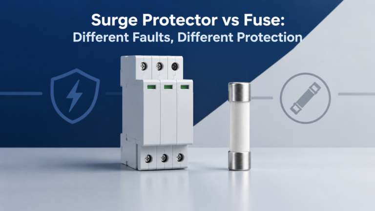
Un protector contra sobretensiones limita las sobretensiones transitorias; un fusible interrumpe las sobrecorrientes. Conoce las diferencias, los límites de los dispositivos combinados y las comprobaciones necesarias para una protección coordinada.
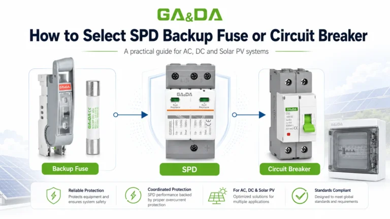
Descubre cómo seleccionar un fusible o un interruptor automático de respaldo SPD para sistemas de protección contra sobretensiones de CA, CC y energía solar fotovoltaica. Evita los errores habituales en el dimensionamiento y la instalación.
Have you ever looked at a fuse label and wondered what all those numbers actually mean? Fuse ratings tell you how a fuse behaves under electrical load, when it should open the circuit, and whether it can safely protect your equipment during a fault. Choosing the correct fuse is not just about matching amperage. You […]