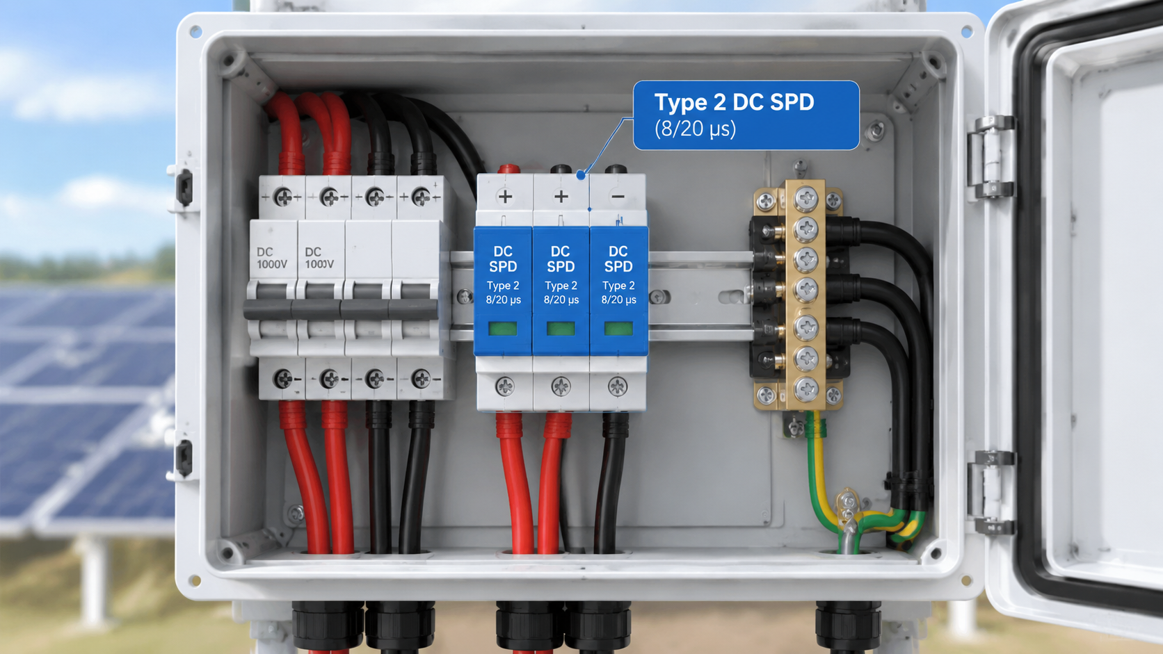
Most solar DC distribution boxes (DCDBs) are fitted with a Type 2 DC surge protection device (SPD), rated for 8/20 µs surge currents; a Type 1+2 DC SPD is required when the DC circuit is exposed to direct lightning strikes or the site has no external lightning protection system. This guide explains how to decide which SPD belongs inside your DCDB, how to match its DC voltage rating to the array, and what to check before you specify a unit — so the box protects the inverter instead of becoming a weak point.
A DCDB is the DC distribution point that combines the output of several PV strings and feeds the inverter, housing the string fuses or DC MCBs, the busbar and the SPD. The term overlaps with “PV combiner box”; on this site the wider role of that enclosure is covered in the guide to solar combiner boxes, while this article focuses on one decision: which SPD type to install inside the DC distribution box, and how to specify it correctly.
Why the SPD inside a DCDB Is Not an Optional Extra
The DC cables running between the array and the DCDB act as long antennas. A nearby lightning discharge induces transient overvoltages on those cables even when the strike never touches the installation; switching events and fuse or breaker operations in the DC circuit add smaller but more frequent transients. Without an SPD at the DCDB, those surges travel straight into the inverter input, the MPPT stage and the DC bus capacitors — the components most likely to fail and the most expensive to replace.
An SPD mounted inside the DCDB, close to the point where the DC cables enter the enclosure and where the busbar feeds the inverter, is the standard way to clamp these overvoltages before they reach sensitive equipment. This is why surge protection is a normal factory-fit option on commercial DCDBs and why retrofitting one is usually the first upgrade recommended for boxes that shipped without it.
ما هو نوع SPD المستخدم في نظام DCDB الشمسي؟
The answer depends on the surge exposure of the DC circuit, not on the size of the box. SPD types are defined by the test waveform they must survive: Type 1 devices are tested with the 10/350 µs waveform that represents direct lightning current, while Type 2 devices are tested with the 8/20 µs waveform that represents induced and switching surges. A Type 1+2 SPD is a single module tested against both. The differences are explained in more depth in the site comparison of Type 1 vs Type 2 surge protective devices.
In practice, two configurations cover nearly every DCDB:
Situation at the site
SPD type fitted in the DCDB
Typical test waveform
Rooftop or small-to-medium system, DC cables are short or already protected by an external lightning protection system (LPS); no direct-strike exposure of the DC circuit
Type 2 DC SPD — the most common choice for DCDBs
8/20 µs
Ground-mounted plant or long, exposed DC cable runs without an LPS; direct lightning strikes can inject current into the DC circuit
Type 1+2 DC SPD, or a Type 1 SPD upstream plus Type 2 inside the DCDB
10/350 µs and 8/20 µs
Waveforms and class definitions follow IEC 61643-11 and IEC 61643-31. Whether a Type 1 capability is required should always be confirmed by a lightning risk assessment for the specific site.
Step 1 — Check whether the DC circuit can be struck directly
If the PV array, the DCDB and the DC cabling are all inside the protected volume of an external lightning protection system (for example, a rooftop system under the building’s LPS), the DC circuit is normally considered not directly exposed and a Type 2 SPD is the right fit. If the array stands in open ground with no LPS, or the DC cables run for long distances outside any protected volume, the DC circuit can carry direct lightning current and the SPD must include a Type 1 stage (10/350 µs capability).
Step 2 — Do the risk check for large or high-exposure plants
For utility-scale and commercial ground-mount plants, the usual specification is a Type 1+2 DC SPD at the DCDB input — one module that survives direct-strike current and still clamps the frequent induced surges. In very large installations the protection is sometimes staged: a Type 1 SPD at the array-side distribution point and a Type 2 SPD at the DCDB output or at the inverter input. Either way the DCDB SPD should be specified from the data sheet, not from the box size: the deciding factors are the site’s lightning exposure and the resulting risk assessment.
Step 3 — For everything else, Type 2 is the standard answer
For residential, commercial rooftop and most C&I systems without direct-strike exposure, the answer to “which SPD is used in a solar DCDB” is a Type 2 DC SPD. It protects the inverter input and the DC bus from induced lightning surges and switching transients, it is compact enough to fit standard DIN-rail space inside the box, and it is the configuration assumed by most DCDB manufacturers as the factory default. For the wider selection process — ratings, application and common mistakes — see the site’s Type 2 DC surge suppressor selection guide.
Matching the SPD Voltage Rating to the DCDB’s DC System
The single most common specification error is buying an SPD whose voltage rating does not match the DC system. The relevant parameter for PV SPDs is the maximum continuous operating voltage, marked Ucpv. The SPD’s Ucpv must stay above the highest voltage the DC circuit can present in continuous operation — for a PV array, the string open-circuit voltage corrected for the coldest expected temperature, not the nominal system voltage alone.
In practical terms this means selecting the next standard Ucpv rating above the array’s maximum open-circuit voltage rather than matching the inverter’s nominal MPPT range. Common Ucpv ratings for PV DC SPDs are roughly 500 V, 600 V, 800 V, 1000 V, 1200 V and 1500 V, and the exact rule of thumb (many manufacturers specify Ucpv ≥ about 1.1–1.2 times the relevant array voltage) should be taken from the SPD data sheet you intend to use. For the high-voltage end, the site’s 1500 V DC SPD selection guide covers 1500 V arrays in detail.
An SPD with a Ucpv below the circuit voltage is continuously stressed and fails early; an SPD with an unnecessarily high Ucpv clamps at a higher voltage and may not protect the inverter. The rating must be matched, not maximised.
SPD Ratings to Check Before the Unit Goes into the Box
Once the type (Type 2 or Type 1+2) and the voltage rating are fixed, confirm the remaining parameters against the data sheet. The table below lists what each rating means for a DCDB application; the full explanations of the SPD parameters are in the site guide to Iimp, In, Imax and Up SPD specifications.
المعلمة
What it means inside a DCDB
Typical value to look for
Nominal discharge current (In)
Surge current the SPD can handle repeatedly in the 8/20 µs test wave without degradation
20 kA per pole is the common specification for DCDB SPDs
Maximum discharge current (Imax)
Highest single 8/20 µs surge the SPD can survive once
40 kA is typical; higher on exposed sites
Voltage protection level (Up)
Clamped voltage the SPD lets through; must be below the inverter input withstand voltage
Depends on Ucpv; confirm against the inverter data sheet
Short-circuit withstand (Iscpv)
PV short-circuit current the SPD terminals can withstand under fault, coordinated with its backup protection
Matched to the DCDB branch rating and the backup fuse/MCB
Remote signal / status contact
Dry contact that reports SPD end-of-life to a monitoring system
Valuable on commercial plants; the visual green/red indicator is the minimum
The green/red status window on the front of the module is the first line of defence — a red indicator means the SPD has reached end of life and no longer protects the circuit, so the module must be replaced and the cause of failure investigated before the system is re-energised.
Where the SPD Goes Inside the DCDB
Positioning inside the enclosure matters as much as the type. Three rules govern almost every correct installation:
Mount the SPD as close as possible to the point of entry of the DC cables. This minimises the length of unprotected conductor between the outside world and the SPD.
Keep every SPD connecting lead short and direct. Long or looped leads add inductance that raises the effective protection level; most data sheets ask for SPD leads of roughly 0.5 m or less, and for the protective earth connection to the DCDB earth busbar to be the shortest conductor of all.
Connect the SPD in parallel with the busbar it protects. The SPD is a voltage-limiting device connected between each DC conductor and earth; it is never wired in series with the load. The wiring arrangement is shown in the site’s solar combiner box wiring diagram , and the DC wiring mistakes that cause most field failures are listed in the guide to surge protective device installation mistakes .
Backup Protection: The SPD in Front of the Inverter Still Needs Protection Itself
An SPD is a sacrificial component by design: at end of life it can fail short-circuit, and a shorted DC SPD on a live array is a fire risk unless the circuit can be interrupted. That is why the SPD branch inside a DCDB is normally protected by its own backup device — a gPV fuse or a DC-rated MCB sized from the SPD data sheet — which also gives maintenance staff a way to isolate the SPD without dropping the whole DC circuit.
The backup device rating is not a free choice: the SPD data sheet states the maximum permissible backup fuse or breaker, and the chosen device must also clear the available PV short-circuit current at the DCDB. Selection of that device is covered step by step in the guide to اختيار الصمامات الاحتياطية أو قواطع الدائرة الكهربائية من نوع SPD.
A Short Specification Checklist for the DCDB SPD
Decide the type from surge exposure: Type 2 for protected or low-exposure sites; Type 1+2 where the DC circuit can be struck directly.
Confirm the SPD is a DC/PV model to IEC 61643-31 , not an AC mains SPD — the fault behaviour and voltage rules differ. See the site’s AC SPD vs DC SPD comparison.
Match Ucpv to the array’s maximum open-circuit voltage (cold-temperature corrected), not to the nominal system label alone.
Verify In (commonly 20 kA), Imax , Up against the inverter withstand, and Iscpv against the DCDB’s available short-circuit current.
Choose a module with a status indicator , and a remote signal contact if the plant is monitored.
Specify the backup protection (gPV fuse or DC MCB) from the SPD data sheet, and keep all SPD leads short with the earth connection shortest of all.
Confirm the SPD’s IP rating and temperature range suit the DCDB’s environment (outdoor boxes see wide temperature swings and, in coastal or high-humidity sites, salt and condensation).
الأسئلة الشائعة
Which type of SPD is most commonly used in a solar DCDB?
The Type 2 DC SPD is the most common fit in a solar DCDB. It protects the DC circuit from induced lightning surges and switching transients with an 8/20 µs capability, which covers rooftop and most commercial systems. Type 1+2 DC SPDs are fitted where the DC circuit is exposed to direct lightning strikes, typically ground-mounted plants and long unprotected DC cable runs.
What is the difference between a Type 1+2 and a Type 2 DC SPD?
The difference is the test waveform each type must survive. A Type 2 SPD is tested with the 8/20 µs wave that represents induced and switching surges. A Type 1+2 SPD is additionally tested with the 10/350 µs wave that represents direct lightning current, so it can carry far more energy in a single event. Type 1+2 modules are used where that direct-strike capability is required by the site risk assessment.
Do I need a Type 1 SPD for a rooftop solar DCDB?
Usually not. If the rooftop array, the DCDB and the DC cabling sit inside the protected volume of the building’s external lightning protection system, a Type 2 DC SPD is normally sufficient. A Type 1 or Type 1+2 requirement appears when the DC circuit can be struck directly or when a lightning risk assessment for the site calls for it.
How do I choose the DC voltage rating of the SPD for my DCDB?
Match the SPD’s maximum continuous operating voltage (Ucpv) to the highest voltage the DC circuit can present — the string open-circuit voltage corrected for the coldest expected temperature — and follow the rating rule on the specific SPD data sheet. Selecting by the inverter’s nominal MPPT voltage alone is a common error that leaves the SPD either overstressed or clamping too late to protect the inverter.
Does the SPD in a DCDB need a fuse or a DC MCB in front of it?
Yes. The SPD data sheet specifies a maximum backup fuse or DC-rated MCB, and that device should be fitted in the SPD branch. It interrupts the PV short-circuit current if the SPD fails short at end of life and lets maintenance isolate the SPD without switching off the whole DC circuit. The backup rating is taken from the SPD data sheet, not chosen freely.
Can one SPD at the DCDB protect the whole PV system?
One correctly specified SPD at the DCDB protects everything downstream of it — primarily the inverter input and the DC bus. It cannot protect equipment connected upstream of its mounting point, and very large or widely spread plants are often protected in stages (Type 1+2 at the array-side distribution, Type 2 at the DCDB or inverter). The SPD’s voltage protection level must also be below the withstand voltage of the inverter it protects, so “one SPD for everything” is only true within those limits.
Conclusion
The SPD inside a solar DCDB is normally a Type 2 DC SPD rated to IEC 61643-31, upgraded to a Type 1+2 module wherever the DC circuit can be struck directly. Whichever type the site calls for, the specification still stands or falls on three details: a Ucpv matched to the real maximum array voltage, a voltage protection level below the inverter’s withstand, and backup protection sized from the SPD data sheet with short, direct wiring inside the enclosure. Nail those and the DCDB does its job — collecting the strings and delivering clean, protected DC power to the inverter.
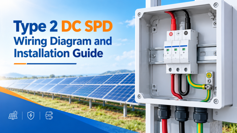
كيفية توصيل وتركيب جهاز حماية من اندفاع التيار المستمر من النوع 2 في نظام الطاقة الكهروضوئية: توصيلات الأطراف، والتوصيلات المتوازية، والصمامات الاحتياطية أو قواطع التيار المصغرة (MCB)، والتأريض، والأخطاء الشائعة.
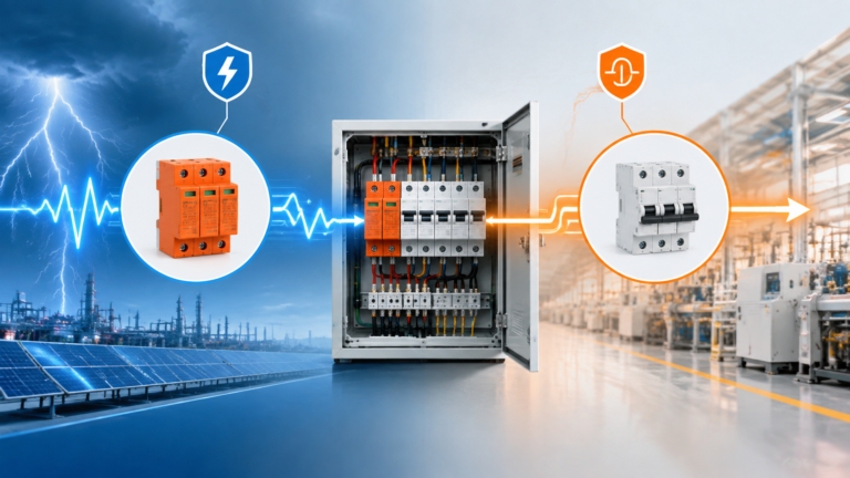
تعمل مانعات الصواعق على كبح الجهد الزائد العابر؛ بينما تعمل قواطع الدائرة على إزالة أحمال الزائد ودوائر القصر. قارن بين وظائفها وتطبيقاتها وتنسيق عملها.
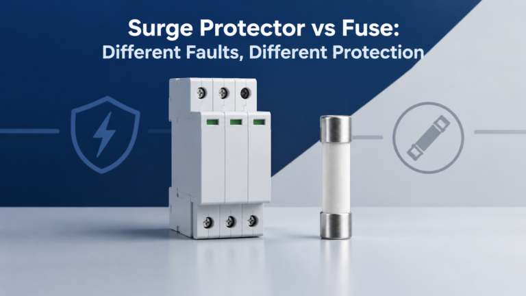
يعمل جهاز الحماية من زيادة التيار على الحد من الجهد الزائد العابر؛ بينما يعمل المصهر على قطع التيار الزائد. تعرف على الاختلافات بينهما، وحدود الأجهزة المدمجة، وطرق الفحص لضمان الحماية المنسقة.