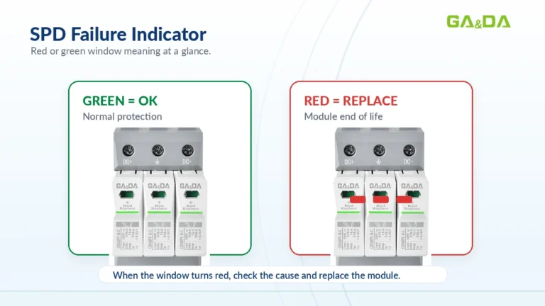





مؤشر عطل نظام SPD: ماذا تعني النافذة الحمراء أو الخضراء؟
يشرح هذا المقال مؤشر أعطال SPD، ومعاني النوافذ الحمراء والخضراء، وأسباب الأعطال الشائعة، وخطوات الاستبدال، ونقاط التلامس الخاصة بالإشارات عن بُعد.
اقرأ المزيد Arabic
A surge protection device can fail without any visible warning, and a protection module that is still sitting on the DIN rail is not proof that your equipment is protected. Knowing how to test a surge protection device safely lets you separate a healthy SPD from one that has reached end of life, and it tells you when the only correct action is replacement.
The safe method is a sequence, not a single measurement: isolate the supply, prove the circuit dead, inspect the module and its connections, then take resistance, leakage or thermal readings with the right instrument and compare them against the manufacturer’s data. This guide walks through that procedure, explains how to read the results, and — just as importantly — explains what an on-site test cannot prove.
Key takeaways
Disconnect and lock off the upstream protective device, prove the terminals are dead with an approved voltage indicator, and discharge any stored energy. Then work through four checks in order: visual and thermal inspection of the module and its terminals, verification that the backup protection is intact, a resistance reading between each live terminal and protective earth, and — where the manufacturer publishes a procedure — an insulation resistance or leakage current measurement. Reconnect, re-energise, confirm the status indication, and record the results against the installation’s previous readings.
What you get from that sequence is a verdict on condition: connected or disconnected, shorted or intact, overheating or cool. What you do not get is a number for how much surge energy the device can still absorb. That distinction is the single most common misunderstanding about SPD testing, and it is the reason manufacturers combine field checks with periodic replacement.
An SPD is connected between live conductors and earth, which means testing it means working on the point in the installation with the highest available fault energy. Treat every test as live work until you have proved otherwise.
Open the upstream protective device — the main switch, the SPD’s dedicated disconnect, or the backup fuse or circuit breaker feeding the SPD — and lock or tag it out so it cannot be re-closed while you work. Then prove the circuit dead at the SPD terminals with an approved two-pole voltage indicator, tested on a known live source before and after the check. Residual charge on the module and on capacitive elements in the panel should be discharged according to the manufacturer’s instructions and the site’s safe working procedure.
Follow the verification and testing requirements that apply to your installation. Standards such as IEC 60364-6 for low-voltage installations and NFPA 70E for electrical safety in the workplace define how isolation and verification must be performed; the SPD manufacturer’s installation instructions define what may be tested and at what voltage.
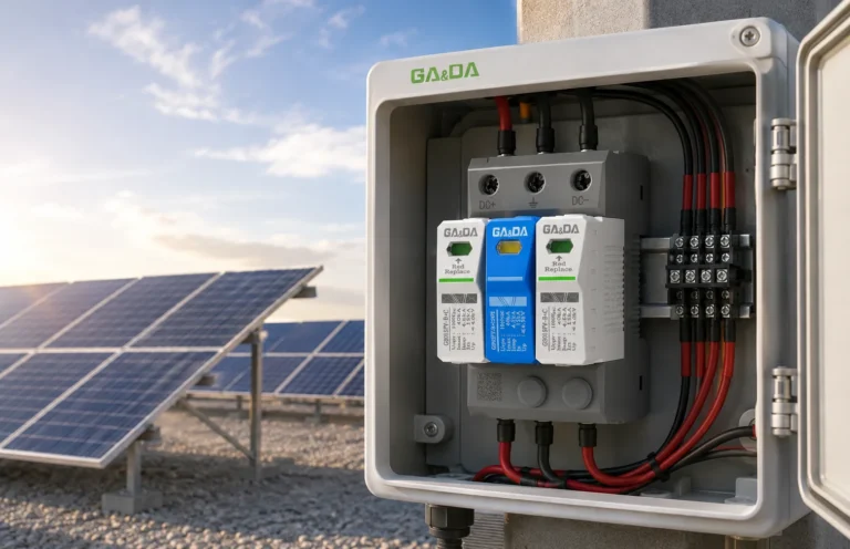
On the DC side of a photovoltaic system, the array is a current source that cannot be switched off during daylight. Opening the DC isolator stops the inverter side, but the string side remains live and energised by the modules. A safe test on a string SPD therefore requires the string to be de-energised at source — for example by opening the string fuses and covering or disconnecting the array — or by working to a documented DC safe-isolation procedure with the appropriate PPE and insulated tools. If your procedure cannot guarantee a dead string, the SPD should be tested by a qualified PV service team, not improvised on a sunny afternoon.

Start with the module itself. Check the status window — most modular SPDs use a red and green indicator linked to the internal disconnector, and the meaning of each colour is worth understanding before you interpret it. What the red or green status window on an SPD actually means is covered in detail in our dedicated guide; in short, a red window indicates the module has operated its disconnector or reached end of life.
Then look for the physical evidence of failure and of stress that has not yet tripped anything:
A thermal scan is most useful when the installation is energised under normal load, before isolation. Warm is normal; a hot module, a hot terminal or a temperature rise that grows over time is not.
Check that the fuse or circuit breaker protecting the SPD has not operated and is of the correct rating. A blown backup fuse or a tripped breaker leaves the SPD connected but unable to perform its function, and the fault can look like an SPD problem when it is not. Selection of that device is a matching exercise rather than a guess: choosing the SPD backup fuse or circuit breaker explains how to coordinate it with the SPD’s short-circuit withstand and with the upstream device.
With the SPD isolated, measure resistance between each live terminal and protective earth, and between poles where the manufacturer defines it, using a multimeter on its resistance range. A healthy metal oxide varistor is a high-impedance element at the low voltage a multimeter applies, so a normal reading is a very high resistance or an open circuit (OL). A reading close to zero indicates a varistor that has short-circuited; a reading that is open where the design expects continuity through a disconnector indicates the internal disconnector has operated.
Two cautions matter here. First, a multimeter continuity “beep” is not a sign of a healthy SPD — advice to that effect circulates widely online and it is wrong for varistor-based devices. Second, some SPD designs include parallel elements or an auxiliary circuit that produces a finite reading, so always compare against a known-good module of the same type or against the manufacturer’s stated value rather than against a generic expectation.
Insulation resistance testing is a defined test with defined conditions, and both come from the standard and the datasheet. For low-voltage SPDs, insulation resistance requirements appear in the product standard — IEC/EN 61643-11 and its national equivalents — and a commonly quoted type-test figure is a minimum of 100 MΩ measured with 1000 V DC applied to the relevant terminal combination on a new sample, under controlled laboratory conditions.
That figure is a type-test criterion, not a field acceptance value, and it must not be applied blindly across the protective path. A DC test voltage above the SPD’s maximum continuous operating voltage will drive the varistor into conduction and produce a low, misleading resistance reading on a perfectly healthy device. Follow the manufacturer’s published field procedure; if none is published, do not improvise one. Disconnect the SPD from the circuit before any insulation test, and discharge it afterwards.
An SPD that is degrading typically shows a rising standing leakage current before any indicator changes colour. Where the manufacturer publishes a leakage limit — often in the region of a few hundred microamps to about 1 mA at rated voltage for low-voltage modules — a reading that has drifted upward against previous records is an early warning.
Measure with the SPD energised under stable system voltage and with a suitably rated instrument for the circuit, working to a live-work procedure with the correct PPE for the installation category. Never introduce an instrument into a circuit it is not rated for, and never open a connection on a live SPD circuit.
If the SPD carries a remote signalling contact — typically marked COM, NO and NC — verify that it changes state when the module is removed or its micro-switch is actuated, and that the signal reaches the alarm, PLC, BMS or SCADA input it is wired to. A contact that no longer operates silently disables the site’s ability to detect failure remotely. Where the SPD includes an event counter, record the count: a rapidly rising count signals repeated surge activity and a module approaching end of life.
Refit the module in the correct orientation, torque the terminals to the manufacturer’s values, and confirm the wiring matches the published diagram — reversed or lengthened connecting conductors degrade protection performance and are among the most common SPD installation mistakes. Re-energise, then confirm the status window, the remote contact and normal system voltage. Record the date, ambient and module temperature, leakage or insulation readings, counter value and any observed damage. A single reading has limited value; a series of readings across maintenance cycles is what shows degradation.
| Observation | Likely meaning | Action |
|---|---|---|
| Green status window, high resistance to PE, cool module | Module connected and not short-circuited | Return to service; record and continue routine checks |
| Red status window | Internal disconnector has operated or the module has reached end of life | Replace the module; investigate the cause before refitting |
| Resistance close to zero between live terminal and PE | Varistor short-circuited; the SPD may be relying on its backup protection | Isolate and replace; check the backup fuse or breaker for stress |
| Module noticeably hot under normal load | Elevated leakage, degraded element or a poor connection | Isolate, inspect terminals and conductors, replace if terminals are sound |
| Backup fuse blown or breaker tripped, SPD indicator still green | Fault or coordination problem rather than proven SPD failure | Investigate the fault, verify backup protection selection, then retest the SPD |
| Leakage creeping upward against previous records | Normal end-of-life degradation of the protective element | Plan replacement at the next scheduled outage |
| Remote contact does not change state | Signalling contact or wiring fault; monitoring is blind | Repair the contact or wiring; do not rely on visual inspection alone |
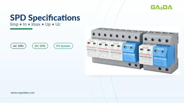
When you replace a module, match the replacement to the original specification rather than to whatever is on the shelf. The classification and the ratings that govern behaviour are not interchangeable between product families: Type 1 and Type 2 SPDs differ in how they are tested and where they belong, and the declared values — Iimp, In, Imax and Up — must be equivalent or better for the installation to keep the protection level it was designed for.
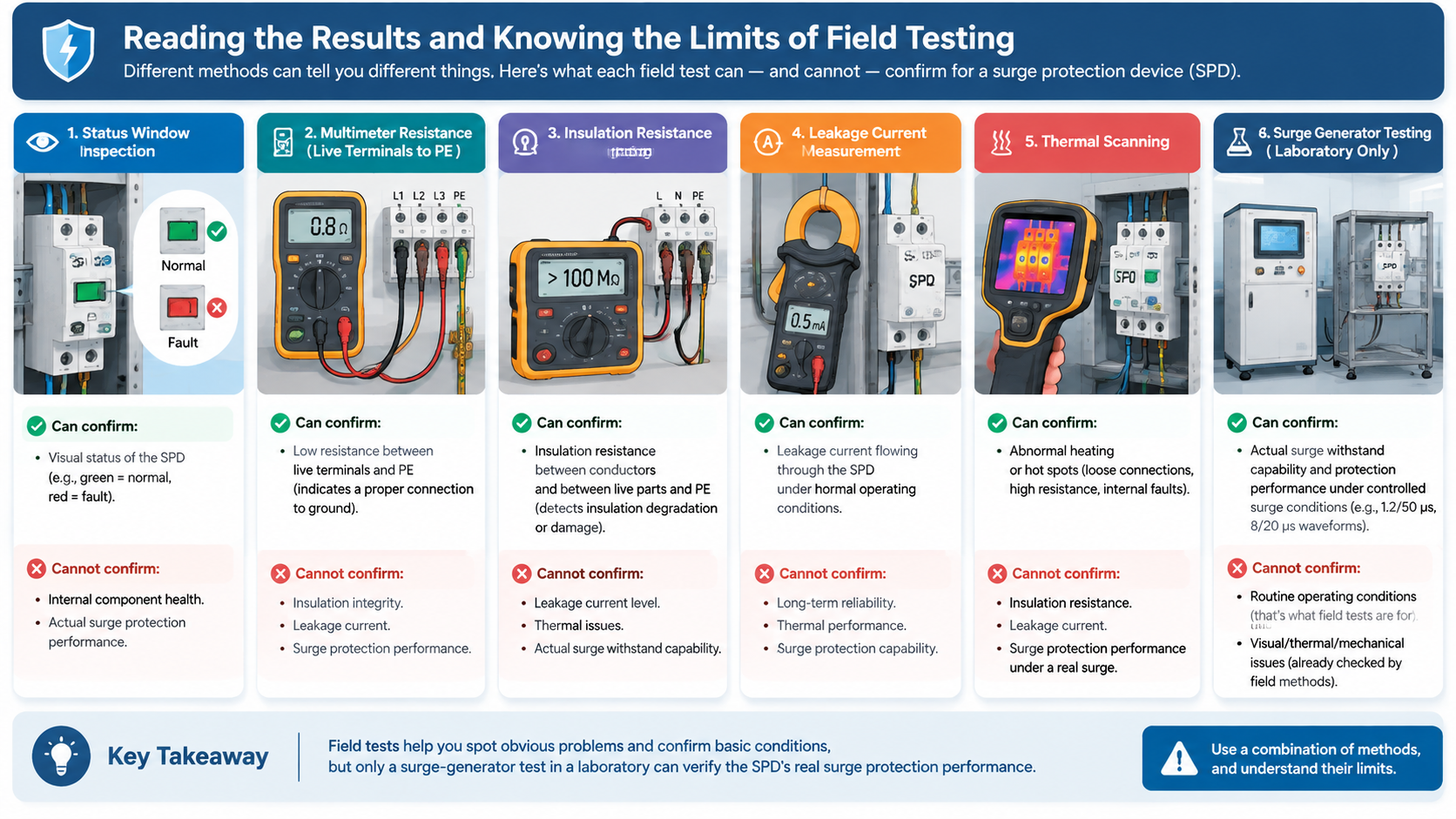
Every instrument available to a maintenance electrician answers a question about condition, not about capacity. Understanding the boundary keeps you from declaring a degraded module healthy.
| Method | What it confirms | What it cannot confirm |
|---|---|---|
| Status window inspection | Whether the internal disconnector has operated | Remaining capacity; a module can be green and still heavily degraded |
| Multimeter resistance / continuity | Open or short condition of the protective element and the wiring | Clamping voltage, response time or remaining surge capacity |
| Insulation resistance test | Insulation integrity where the manufacturer defines a procedure | Protective performance; results depend on test voltage and terminal combination |
| Leakage current measurement | Whether standing leakage has drifted from previous readings | A capacity figure; it is a trend indicator that needs a baseline |
| Thermal imaging | Abnormal heating indicative of degradation or a bad connection | Anything about an SPD that is degraded but still cool |
| Impulse test with a surge generator | Residual voltage and behaviour under a defined 8/20 µs impulse | Not a field test: it requires laboratory equipment and a controlled environment |
The impulse test is the only method that measures what the SPD actually does during a surge. It applies a defined current waveform to the device, records the residual voltage across the terminals and checks that the module survives. Because it requires calibrated impulse generation and a safe test enclosure, it belongs to manufacturers and accredited laboratories — which is why field practice pairs periodic inspection with planned replacement instead of trying to measure remaining life on site.
That has a practical consequence: an SPD that passes every field check may still be at the end of its useful life. A module that has absorbed many events, that has been in service for many years in a lightning-exposed location, or that is installed in an installation whose fault level has since increased, should be replaced on a schedule or after significant events, not only after it has failed a test.
Testing frequency follows exposure and criticality rather than a universal interval. A defensible maintenance approach includes:
For PV installations, add an inspection after any string fault, inverter trip or combiner box alarm. Where a string SPD is DC-rated for the system voltage — for example a module selected for a 1500 V DC PV system — the same condition checks apply, but the isolation procedure must follow the DC safe-working rules described earlier.
You can use a multimeter to check whether the protective element is open or shorted and whether the wiring and terminals are sound, provided the SPD is isolated and proved dead. You cannot use a multimeter to measure how much surge capacity remains, because it applies only a few volts and the device only reacts at hundreds of volts.
For a varistor-based module, a very high resistance or an open-circuit reading is normal at multimeter test voltage, because the element is not conducting. A reading close to zero suggests a shorted varistor. Always compare against the manufacturer’s data or a known-good module of the same type, because auxiliary circuits in some designs produce a finite reading.
Visual inspection, thermal scanning and leakage current measurement are performed with the system energised, and they require a live-work procedure with the correct PPE for the installation. Resistance and insulation resistance measurements require the SPD to be isolated and proved dead first. Never open a connection on a live SPD circuit.
No. A green window means the internal disconnector has not operated, so the module is still connected. It does not confirm remaining capacity, correct selection for the system voltage, or sound wiring and grounding. A module can be green and substantially degraded.
Look at the pattern of evidence. Repeated failures at the same site, discoloured terminals, a blown backup fuse or elevated leakage all point to causes other than a single surge event — wrong voltage rating, poor grounding, incorrect backup protection or an undersized type for the exposure. Check the installation against the published requirements before fitting another module.
Yes, for two reasons. The array remains live in daylight, so isolation must de-energise the string at source. And DC protection devices are not interchangeable with AC ones — the module must be DC- or PV-rated for the system voltage, and any field measurement must stay within the values the manufacturer permits.
Testing a surge protection device safely comes down to process rather than instrumentation. Isolate and prove dead, inspect the module, the terminals and the backup protection, take resistance or leakage readings within the limits the manufacturer publishes, and record what you found. Accept the boundary of field testing: it tells you the condition of the device, not its remaining capacity, and a module that passes every check can still be at the end of its life.
When a module has failed, when it shows signs of degradation, or when the installation has changed since it was selected, replace it with an equivalent or better specification rather than an approximate one. You can review GA&DA surge protection devices for AC, DC and PV applications to match a replacement to your system voltage, SPD type and backup protection — or send us the existing nameplate data and we will confirm the closest equivalent before you place an order.