Solar Combiner Box Wiring Diagram: How to Connect PV Strings, Fuses, SPD and Inverter
Published: Author: Rachel
A combiner box can look straightforward from the outside: several PV string cables enter, and one larger DC circuit leaves for the inverter. The difficulty starts when you open the enclosure. Positive and negative conductors follow different paths, string fuses protect individual circuits, the SPD sits on a surge-protection branch, and the main output must match the inverter and MPPT arrangement.
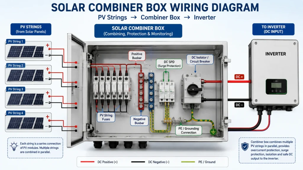
That is why a solar combiner box wiring diagram is more useful than a simple list of components. It shows where each string is protected, where currents are combined, and how the final DC output reaches the inverter.
How to Read a Solar Combiner Box Wiring Diagram
A typical DC-side arrangement can be simplified as:
IEC 62548-1 covers PV array design requirements including DC wiring, electrical protection, switching and earthing. IEC 61643-31 separately covers surge protective devices intended for the DC side of photovoltaic installations up to 1500 V DC.
Read the drawing from the PV array toward the inverter. Follow one string first, then identify the point where several strings become one common output circuit.
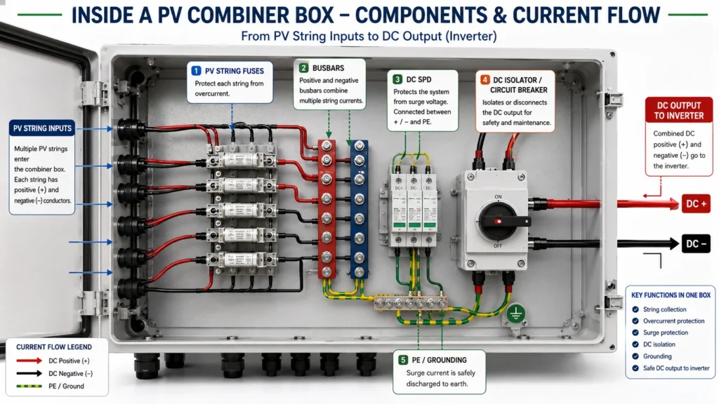
What Each Connection Means Inside the Box
Understanding each connection separately makes a solar combiner box wiring diagram much easier to follow.
PV String Inputs and Fuse Circuits
Each incoming PV string normally has a positive and negative conductor. Where string overcurrent protection is required, the applicable conductor passes through a PV-rated fuse or another specified protective device before joining the common DC circuit.
The fuse is associated with an individual string. Its role is different from that of the main DC switch or breaker on the output side.
Actual string-combiner products may use different protection arrangements depending on string quantity, voltage, MPP tracker configuration and equipment design, which is why the project’s connection diagram should always take priority over a generic drawing.
Busbars and the Combined Output
After the string circuits enter the box, they are collected on the appropriate positive and negative busbars or terminal system.
Series-connected modules establish the voltage of each string, while paralleling comparable strings increases the available current at the common output.
The outgoing circuit may therefore need a much higher current rating than any single string. This affects the busbar, output terminals, switching device and outgoing conductor.
SPD and Protective Earth
The DC SPD is not simply another device placed in series between the array and inverter.
Its purpose is to limit transient overvoltage and divert surge current through the intended protective path. IEC 61643-31 defines the requirements for PV DC SPDs, while IEC 61643-32 addresses their selection, installation and coordination in PV systems.
A solar combiner box wiring diagram should therefore show how the SPD connects to the relevant DC conductors and protective earth. The actual topology and conductor routing must follow the selected SPD, grounding arrangement and project protection design.
Main DC Isolator or Breaker
The combined circuit normally leaves the busbar section through a DC switch-disconnector, DC breaker or another specified device.
Its voltage and current ratings must match the complete output circuit, not one individual string.
Phoenix Contact, for example, offers combiner configurations integrating string collection, fuses, surge protection and DC disconnection as separate functions within the same enclosure.
Step-by-Step Solar Combiner Box Wiring Logic
Step 1: Identify and Verify Every PV String
Give each string a fixed identifier such as:
String 01
String 02
String 03
String 04
Use the same identifiers on cables, drawings and combiner terminals.
Before connection, verify positive and negative polarity. Do not rely only on cable color or previous labeling. A reversed string becomes particularly problematic once it is connected in parallel with correctly wired strings.
The solar combiner box wiring diagram should make polarity clear at every input, through the protection devices, at the busbars and at the final output.
Step 2: Connect Each String to Its Assigned Input
Each PV string is routed to the input position specified by the project drawing.
Where fuses are used, the conductor passes through the appropriate fuse holder before reaching the common collection point.
Terminals, lugs, conductor sizes and tightening torques should follow the requirements of the actual equipment. Poor termination can create localized heating, so connection quality matters just as much as correct circuit routing.
Step 3: Combine the Strings at the Busbars
Once the input circuits are protected and identified, they connect to the positive and negative bus system.
At this stage, consider the combined output current rather than only the current of one string.
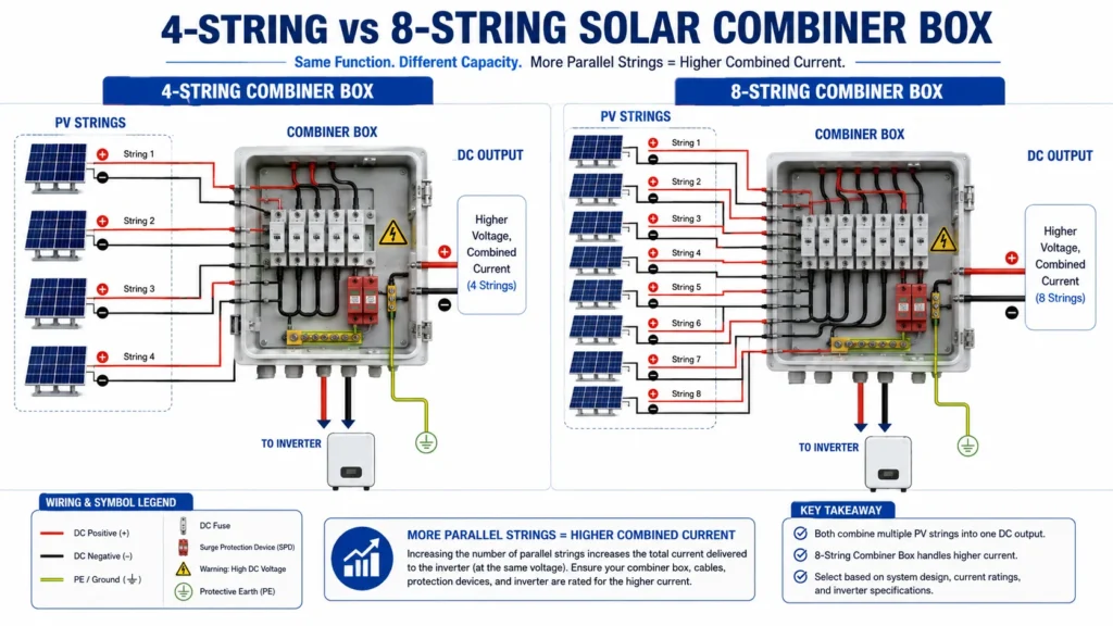
Eight parallel strings can demand substantially more from the common output circuit than four comparable strings. The output section must therefore be designed for the total circuit rather than copied from the input side.
Step 4: Connect the SPD and PE Path
The SPD is connected according to the specified PV surge-protection topology.
IEC 61643-32 specifically addresses the selection, installation and coordination of SPDs used in photovoltaic systems up to 1500 V DC.
Conductor arrangement should therefore follow the SPD manufacturer’s instructions and the project’s surge-protection design rather than simply placing the device wherever space remains inside the enclosure.
Step 5: Connect the Common Output to the Inverter
The final DC positive and negative conductors leave the combiner box and connect to the intended inverter input.
Before energizing the circuit, verify:
Output polarity
Maximum DC voltage
Combined current
Output conductor size
Terminal capacity
Switching-device rating
Inverter input assignment
MPPT configuration
Strings should be combined according to the inverter’s electrical architecture, not simply because spare inputs are available inside the box.
4-String vs 8-String Combiner Box Wiring
The basic solar combiner box wiring diagram does not fundamentally change when the number of strings increases, but the electrical requirements do.
Item
4-String Combiner Box
8-String Combiner Box
PV string inputs
4
8
Individual string circuits
4
8
Parallel current
Lower for comparable strings
Higher for comparable strings
Busbar/output requirement
Based on 4-string design current
Based on 8-string design current
Output conductor
Project-specific
Project-specific
MPPT compatibility
Must be checked
Must be checked
An 8-string box should therefore not be treated as nothing more than a 4-string box with four additional terminals.
Higher parallel current can change the required busbar capacity, disconnect device, cable, terminal arrangement and thermal design.
Commercial products also demonstrate this distinction clearly: PV string combiner boxes are offered with different string counts, voltage ratings, fuse arrangements and output equipment rather than as one universal design.
How MPPT Configuration Changes the Wiring
A solar combiner box wiring diagram should also reflect how the inverter tracks the PV array.
Multiple Strings on One MPPT
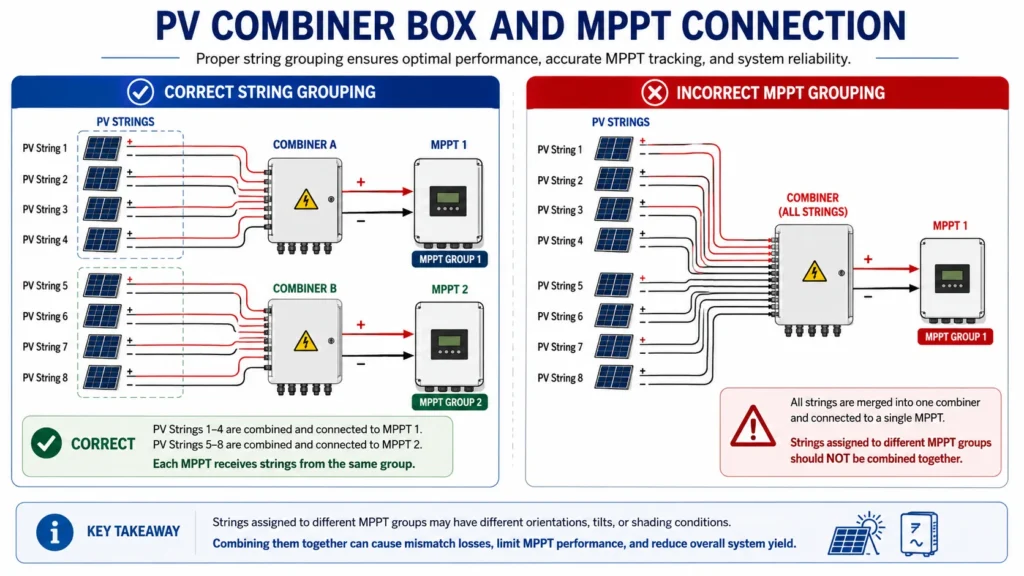
Several electrically compatible strings may be paralleled for one MPPT when the inverter and system design permit it.
In this arrangement, the combiner box collects the designated strings and sends the resulting DC circuit to the corresponding inverter input.
Systems with Multiple MPPTs
Now consider an installation with eight PV strings.
If the inverter design assigns:
4 strings to MPPT 1
4 strings to MPPT 2
then simply combining all eight strings into one output would not follow the intended inverter architecture.
This is not just theoretical. Commercial string combiner products are specified with both number of strings and number of supported MPP trackers, and connection diagrams can show separate string-to-MPPT paths.
For that reason, the solar combiner box wiring diagram should always be checked against the inverter connection plan.
Common Wiring Mistakes to Avoid
A technically correct diagram can still be implemented badly in the field.
Common mistakes include:
Reversing one PV string
Combining strings assigned to different MPPT groups
Using a protective device with an unsuitable DC rating
Treating the SPD like a normal series device
Ignoring the combined output current
Using an undersized output cable
Leaving terminals loose or using unsuitable lugs
Creating poor protective-earth connections
Leaving unused cable entries unsealed
Copying a solar combiner box wiring diagram from another model without checking the actual product
The last mistake is especially easy to make because many boxes look similar internally.
Actual manufacturer connection drawings show that string count, MPPT arrangement, SPD topology and internal connection paths can vary from one SCB configuration to another.
Checks Before Energizing the Combiner Box
A short table is more useful here than another long installation checklist.
Check
Why It Matters
String identification
Confirms each cable matches the drawing
Polarity
Prevents reverse connection
String voltage
Helps identify abnormal strings
Fuse/device rating
Confirms correct PV DC protection
Terminal condition
Reduces connection-heating risk
SPD and PE connection
Confirms the intended surge-protection path
Output polarity
Protects downstream equipment
Output cable
Matches the combined output circuit
MPPT assignment
Matches inverter architecture
Cable glands and seals
Maintains enclosure protection
PV modules can remain electrically active while exposed to light. Wiring, electrical measurements and commissioning should therefore be handled by qualified personnel using procedures and test equipment appropriate to the PV DC system. IEC 62548-1 treats installation, wiring, switching and protective measures as part of the PV array design framework.
FAQ About Solar Combiner Box Wiring Diagram
How do you wire a solar combiner box?
Individual PV strings enter dedicated input circuits, pass through the required string protection and connect to the positive and negative collection system. The combined circuit then passes through the specified DC switching or protection device before reaching the inverter. The SPD and PE circuit follow the project’s surge-protection design.
Where does the SPD connect in a solar combiner box?
The PV DC SPD is connected as part of a parallel surge-protection path according to its topology and the system grounding arrangement. It does not normally carry the array’s full operating current in series.
Does every PV string need a fuse?
Not necessarily. The requirement depends on the parallel string arrangement, module ratings, possible reverse current, conductor protection and applicable electrical rules. The actual protection arrangement should come from the project design rather than a generic diagram.
Can several PV strings connect to one MPPT?
Yes, where the inverter and PV design allow compatible strings to operate in parallel on that MPPT. Strings allocated to separate independent trackers should not be combined merely for convenience.
What happens if a PV string is connected with reverse polarity?
Reverse polarity creates an abnormal circuit condition and can damage equipment or protective devices. Polarity should be verified before strings are paralleled and before the common output is connected to the inverter.
Can I use the same solar combiner box wiring diagram for every project?
No. String count, fuse arrangement, SPD topology, grounding, MPPT configuration, output devices and inverter connections can vary.
A generic solar combiner box wiring diagram is useful for understanding the electrical principle, but installation should follow the actual combiner box connection diagram, inverter documentation and project design.
Final Thoughts
A good solar combiner box wiring diagram lets you follow one clear electrical path.
Each PV string enters as an identifiable circuit, passes through the required protection, joins the correct positive and negative collection points, and becomes part of a common DC output. The SPD provides a separate surge-protection path, while the output switching device and conductors carry the combined circuit toward the correct inverter input.
The number of strings may change, but the principle remains the same: preserve polarity, keep circuits identifiable, combine only strings intended to operate together, and make sure the common output matches the electrical requirements of the complete PV array.
Once those relationships are clear, reading a 4-string, 8-string or larger solar combiner box wiring diagram becomes far easier—and far more useful than simply memorizing where each wire goes.
Why a solar combiner box needs both a DC MCB and a DC SPD: the division of labour between overcurrent and transient overvoltage protection, why neither device can substitute for the other, how they coordinate on the DC bus including the SPD backup protection requirement, and how the pairing changes between 1000 V DC and 1500 V DC systems.
“Combiner box vs junction box” is one of the most common points of confusion in PV design, and it is not a cosmetic one. The two enclosures look similar on a wall, are both described loosely as “the box where the strings are terminated”, and are not interchangeable. A junction box is a passive termination […]
Solar combiner box maintenance is the cheapest protection a PV asset can buy. A short scheduled inspection finds a hardening door gasket, a slack terminal or a saturated desiccant while they are still minor defects; the same three found two years later are an earth fault, a discoloured busbar and a lost production week. This […]