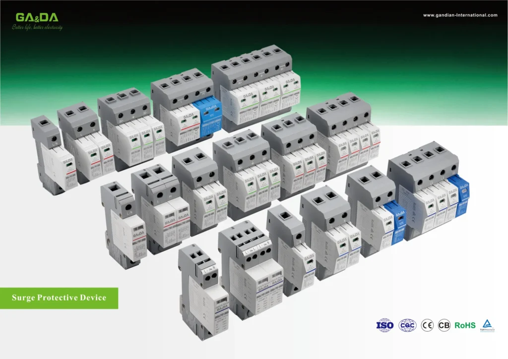
SPD
Fuse Ratings Explained Current Voltage Interrupting Capacity Guide
Learn all about fuse ratings including current, voltage, interrupting capacity, and how to choose the right fuse for safe circuit protection.
Read More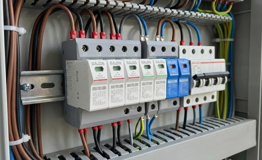
Getting surge protective device installation mistakes under control is one of the fastest ways to improve the real‑world performance of surge protection in low‑voltage systems. Many electrical failures blamed on “bad equipment” are actually the result of incorrect wiring, poor earthing, or wrong device selection rather than the surge protective devices themselves. For example, installing a high‑quality Type 2 SPD such as the G2040DZ Type 2 AC surge protective device 40kA in the right place and in the right way often makes a much bigger difference than simply choosing the most expensive product.
This article focuses on the most common installation mistakes with surge protective devices and offers clear, practical ways to avoid them. It covers wiring layout, lead length, earthing and bonding, SPD selection, and maintenance, using real product examples from low‑voltage AC and PV DC applications so you can translate good practice directly into your next panel design or site installation.
Surge protective device installation mistakes are costly because they silently degrade the protection level while still giving the impression that the system is protected. A poorly installed SPD can have a clamping voltage hundreds of volts higher than expected due to inductive voltage drops along long leads or poor earthing, allowing surges to stress insulation and semiconductor devices. In some cases, the surge protective device installation mistakes are so severe that the SPD fails prematurely, leaving the system effectively unprotected without any obvious warning to maintenance staff.
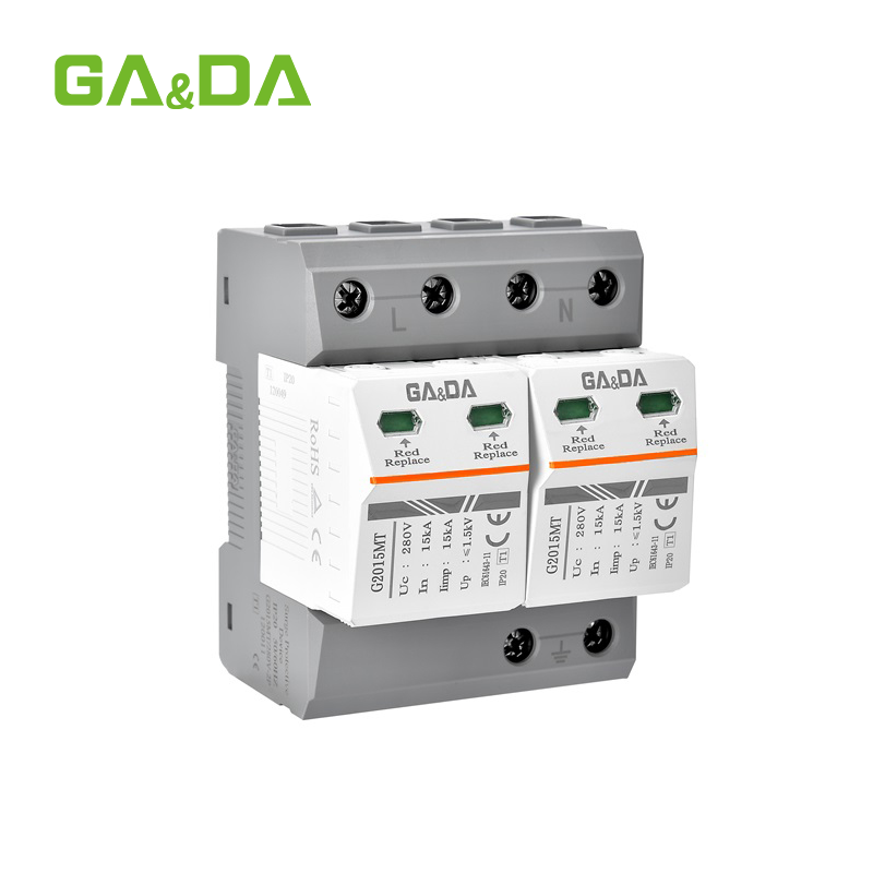
From a risk perspective, the cost of correcting surge protective device installation mistakes is almost always lower than the cost of equipment downtime, warranty claims, or fire damage caused by inadequate surge protection. Modern SPDs, such as the G2015MT Type 1 surge protective device for main distribution, are engineered and tested to perform to their datasheet ratings, but only if their installation follows basic rules for conductor length, cross‑section, and coordination with upstream protection. Failing to respect these details is equivalent to installing a circuit breaker and never tightening its terminals.
Product illustration – main distribution surge protective device
A typical example for correcting early‑stage surge protective device installation mistakes at the service entrance is the G2015MT Type 1 surge protective device for main distribution, which should be mounted close to the main busbars with short, straight conductors.
(Insert G2015MT product image here and link it to the URL above.)
Many of the most common installation mistakes with surge protective devices are related to wiring and physical layout in the panel. Even when the surge protective devices are correctly selected and located in the right distribution board, poor cable routing, long leads, or incorrect terminals can drastically increase the effective protection level. Engineers and installers should therefore treat wiring around SPDs as part of the protective function, not as an afterthought.
Another frequent wiring‑related surge protective device installation mistake is mixing power and signal SPDs haphazardly, without regard for their specific connection diagrams. Power SPDs must be connected between phases, neutral and earth as specified, while signal SPDs must follow the communication or control wiring polarity and shielding scheme. Incorrect wiring can bypass the SPD entirely, leaving sensitive equipment exposed even though a device is physically present in the panel.
One of the best‑known surge protective device installation mistakes is allowing excessive lead length between the SPD and the busbars or earth bar. During a surge, these leads behave like inductors, adding voltage drop proportional to the rate of rise of the surge current. Even a few tens of centimeters of unnecessary lead length can add hundreds of volts to the let‑through voltage, defeating the purpose of the surge protective device.
To avoid this, install SPDs as close as possible to the point being protected, typically near the main or distribution busbars. Use short, straight conductors with minimal loop area, and avoid routing SPD leads in parallel with unprotected signal or control lines. Where possible, use a “V‑connection” or bridged layout, where the SPD is connected between the phases and a nearby earth point using the shortest possible paths. This simple wiring discipline is one of the most effective ways to eliminate wiring‑related surge protective device installation mistakes.
Product illustration – compact Type 2 SPD near busbars
A device like the G2025XZ compact Type 2 surge protective device is designed to fit close to DIN‑rail busbars, making it easier to keep conductors short and reduce wiring‑related surge protective device installation mistakes.
(Insert G2025XZ product image here and link it to the URL above.)
Another widespread wiring mistake is connecting surge protective devices to the wrong terminals, such as tapping from distant branch circuits instead of from the main busbars. This can result in some loads being effectively unprotected, while others experience excessive let‑through voltage due to the added impedance of long feeder sections. In three‑phase systems, reversing or omitting neutral connections, or confusing PEN and PE points in TN‑C or TN‑S systems, are also common sources of surge protective device installation mistakes.
To prevent these errors, always follow the connection diagrams provided by the SPD manufacturer, and double‑check that each surge protective device is connected across the intended conductors (L‑L, L‑N, L‑PE, N‑PE) for the specific earthing system. Marking SPD feeders clearly in the panel and using dedicated terminals or busbar adaptors reduces the risk that future modifications will introduce connection‑related surge protective device installation mistakes.
Earthing and bonding practices have a direct impact on the performance of surge protective devices, and poor grounding is one of the most serious surge protective device installation mistakes. An SPD can only divert surge energy effectively if it has a low‑impedance path to the reference earth potential; high resistance, long earth leads, or floating reference points all raise the effective protection level. This is especially critical for Type 1 SPDs that handle lightning currents and for PV or outdoor installations where potential differences can be large.
Engineers should therefore treat the earthing system as an integral part of surge protection. This includes ensuring that the main earthing terminal is robust, that bonding conductors between subsystems are correctly sized, and that all surge protective devices share a common reference point where possible. When earthing is poorly executed, even the best surge protective devices cannot perform to specification, and installation mistakes with surge protective devices will show up as unexplained damage during storms or switching events.
Product illustration – surge protective devices tied to strong earth
High‑energy SPDs such as the G20100DZ 100kA Type 1 surge protective device rely on a solid connection to the main earthing system to safely discharge large surge currents without causing dangerous potential rises in the installation.
(Insert G20100DZ product image here and link it to the URL above.)
A subtle but serious surge protective device installation mistake is using undersized or overly long earth conductors for SPDs. Thin or excessively long grounding leads can overheat under surge conditions, add significant impedance, and create large potential differences between different parts of the installation. This not only increases the stress on equipment but also raises touch voltages during surge events, which can pose a safety risk.
Best practice is to follow the SPD manufacturer’s recommendations for minimum cross‑section and maximum length of grounding conductors, often requiring at least several square millimeters of copper with a length kept well below half a meter where possible. Routing earth conductors directly to a nearby busbar or chassis point, rather than looping them through distant terminals, minimizes impedance and helps avoid these grounding‑related surge protective device installation mistakes.
Another area where surge protective device installation mistakes appear is in potential equalization. If only some metallic parts and circuits are bonded properly, surge currents may seek unintended paths through signal cables, piping, or structural steel. This is especially problematic in buildings with mixed power, communications, and PV or antenna systems, where surge currents can couple between separate subsystems.
To avoid this, engineers should design a clear bonding strategy that brings all relevant metalwork and system earths to a common reference point, often near the main distribution board where Type 1 SPDs are installed. Local bonding bars in sub‑distribution boards and near sensitive equipment can also help maintain equal potential during surges. This integrated approach to bonding significantly reduces the likelihood that partial or inconsistent bonding will create hidden surge protective device installation mistakes.
Many surge protective device installation mistakes start at the selection stage, long before anyone pulls a cable. Choosing the wrong SPD type, voltage rating, or energy rating for a given location can lead to nuisance tripping, premature end‑of‑life, or inadequate protection. For example, using only a Type 2 SPD at a service entrance that truly requires a Type 1 unit is a classic selection‑level surge protective device installation mistake that can leave the building vulnerable to direct lightning currents.
To avoid these pitfalls, engineers should always start by identifying the system voltage, earthing arrangement, and location within the protection hierarchy (service entrance, distribution board, final circuits, PV DC strings, data or control lines). SPDs must then be chosen with appropriate maximum continuous operating voltage (Uc), discharge current ratings (Iimp, In, Imax), and voltage protection level (Up). Coordination between upstream Type 1 and downstream Type 2 SPDs is crucial; the downstream devices should have equal or lower Up and be rated to handle the residual energy passed on by the upstream units.
Signal and data circuits introduce an additional axis of complexity. Dedicated RJ45 or control line SPDs must match the interface type and bandwidth, and misapplying power SPDs on signal lines, or vice versa, is another frequent surge protective device installation mistake. Using specialized devices such as the G20POE integrated power and network surge protector or the G2010R 24/48/110/220V control signal line surge protector helps ensure that both power and data paths have correctly selected protection.
Even when surge protective devices are installed correctly, time and surge exposure gradually age their internal components. Ignoring inspection and maintenance is therefore another common surge protective device installation mistake, because it assumes that SPDs will protect indefinitely without verification. In reality, high‑energy surges, repeated smaller events, and thermal stress can all degrade MOVs, GDTs, and other elements inside the SPD.
To maintain protection performance, engineers and facility managers should incorporate SPD checks into routine maintenance schedules. This includes inspecting visual indicators or status windows on modular devices, verifying that remote signaling contacts report correctly to monitoring systems, and replacing plug‑in modules that have reached end‑of‑life. It is also prudent to re‑torque terminals periodically, as vibration and thermal cycling can loosen connections over time, re‑introducing surge protective device installation mistakes that were not present at commissioning.
For critical installations, keeping a documented SPD register with installation dates, model numbers, and any recorded surge events helps plan proactive replacements instead of waiting for failures. When combined with periodic infrared inspections and insulation tests on nearby equipment, this approach ensures that surge protective devices continue to do their job quietly in the background for many years.
Q1. What is the most serious installation mistake with surge protective devices?
One of the most serious mistakes is installing an SPD with long, looped leads between the device and the busbars or earth bar. This adds significant inductive voltage drop during surges, raising the effective protection level and allowing damaging voltages to reach equipment even though a surge protective device is present.
Q2. Can I connect several surge protective devices to the same breaker or terminal?
Only if the breaker, terminal, and SPD manufacturer explicitly allow multiple conductors or “double tapping.” Otherwise, sharing terminals can lead to poor contact, overheating, and non‑compliant installations. The safer practice is to provide dedicated terminals, busbar adaptors, or appropriately rated distribution blocks for each SPD connection.
Q3. Do surge protective devices need their own grounding conductor?
Every SPD needs a low‑impedance connection to the earthing system, but this does not always require a separate earth bar. What matters is that the earth conductor is short, appropriately sized, and bonded to the main earthing terminal or local bonding bar so that surge currents have a clear, low‑resistance path to earth.
Q4. How often should surge protective devices be inspected?
Inspection intervals depend on the surge environment and criticality of the installation, but many operators include SPDs in annual or bi‑annual preventive maintenance. In high‑risk or mission‑critical sites, more frequent visual and functional checks may be justified, especially after severe storms or known surge events.
Learn all about fuse ratings including current, voltage, interrupting capacity, and how to choose the right fuse for safe circuit protection.
Read More
Discover GA&DA DC MCBs with advanced arc quenching technology for reliable solar PV battery and EV charging protection up to 1000V DC applications.
Read More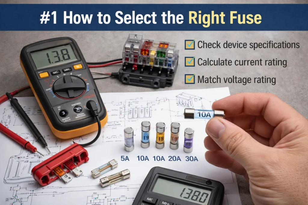
Learn how to select the right fuse with expert tips on fuse types ratings and safety for home automotive and industrial applications.
Read More