RS485 and PLC I/O Surge Protection: Wiring and Grounding
Publicado: Autor: Rachel
RS485 and 24 V PLC I/O are the two interfaces that fail most often in industrial installations, and they fail for a reason that has nothing to do with the data rate. Both run on long cables between cabinets that sit on different earth references. When lightning or a switching event raises the potential of one cabinet relative to the other, the difference appears across the signal pair, and the transceiver at one end sees a common-mode voltage far outside its design range.
Protection for these interfaces follows the same principle as analogue loops — clamp below the device’s withstand, keep the series impedance low enough not to disturb the signal — but the details differ, because RS485 is a terminated bus and a PLC input is a single-ended 24 V circuit.
What actually damages an RS485 port
The transceiver is specified for a common-mode range of about −7 V to +12 V relative to its own ground. Anything beyond that, even briefly, forward-biases internal structures that were never meant to carry current. Three mechanisms get you there:
Ground potential rise. A surge on the power system, or a nearby strike, raises the earth potential at one end of the cable. The transceiver at the other end sees the difference.
Inductive coupling. A long signal cable running parallel to a motor cable or a feeder picks up a voltage along its length.
Direct coupling through the shield. If the shield is bonded at one end and floating at the other, the cable becomes an antenna with a capacitor at one end.
All three are common-mode events. That is why the earth connection of the SPD is not a detail: the device can only clamp what it can reference.
Choosing the device
Uc. Set above the transceiver’s common-mode range with margin. The standard range is −7 V to +12 V, so a device with a Uc around 12 V to 15 V is typical for RS485. A device with a much higher Uc leaves the port exposed; one with a lower Uc conducts during normal operation and loads the bus.
In. 5 kA with an 8/20 µs waveform is the common rating for a bus entry device. Higher ratings are available for exposed runs.
Bandwidth and capacitance. The protection element sits across the pair and therefore adds capacitance. At 9,600 baud this is irrelevant; at 12 Mbit/s it is not. Check the device’s stated data rate rather than assuming any signal SPD will do.
Series resistance. Three-stage devices include series resistors between the discharge stage and the clamping stage. That resistance is what makes the fine clamping possible, and it also adds to the bus load. On a bus with 32 nodes and long cable, the accumulated effect is small but should be checked on marginal installations.
Interface
Typical Uc
Typical In (8/20)
Notas
RS485 / RS422
12–15 V
5 kA
Must pass the data rate without distortion; 3-stage preferred
24 V DC digital input
30–60 V
5 kA
Single-ended; the 0 V reference is part of the circuit
24 V DC transistor output
30–60 V
5 kA
Check the continuous current rating, not just the surge rating
Relay output
Depends on the switched circuit
5 kA
Contact protection is a separate RC or diode network
0-10 V analogue
15–30 V
5 kA
Watch leakage rather than series resistance
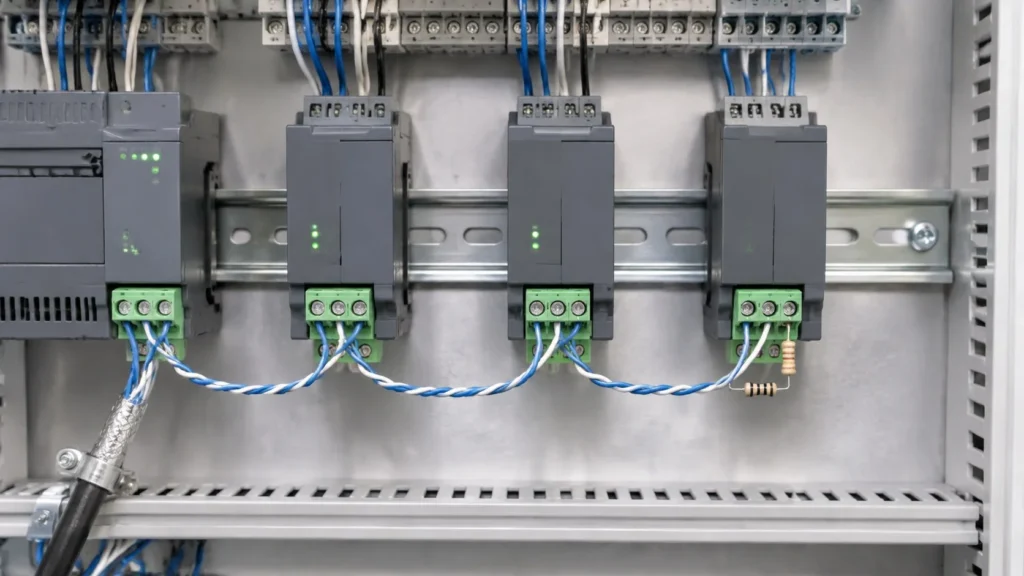
Daisy chain, not star: one pair running from node to node, with the terminator at the physical end of the bus.
RS485 is a bus, and the topology decides whether protection works
RS485 is designed as a daisy chain: one pair running from node to node, with a 120 Ω termination resistor at each physical end. Two habits break it.
Star wiring. Running a separate pair from a central point to each device produces stubs that reflect the signal and create standing waves. It also means a surge entering on one branch has several parallel paths into the same transceiver. If the installation is already star-wired, an RS485 repeater or a hub is a better fix than more protection.
Termination in the wrong place. The 120 Ω resistors belong at the two physical ends of the bus, not at the master and not at every node. If an SPD is inserted between the terminator and the cable, the termination no longer terminates the line.
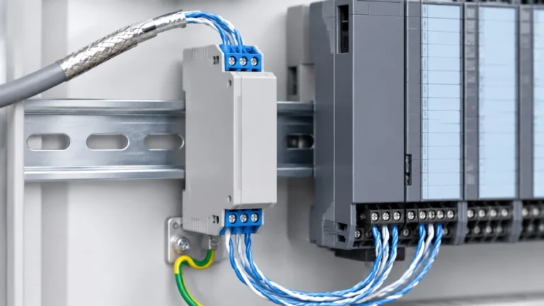
Protection goes where the cable enters the enclosure, not at the transceiver pin. A device fitted inside the cabinet on a short tail protects the transceiver from what gets past the entry point, which is not the same thing.
Shield and earth: one point, not two
The shield is there to intercept capacitive coupling before it reaches the pair. It only does that if it is bonded to earth, and it only avoids becoming a current path if it is bonded at one point.
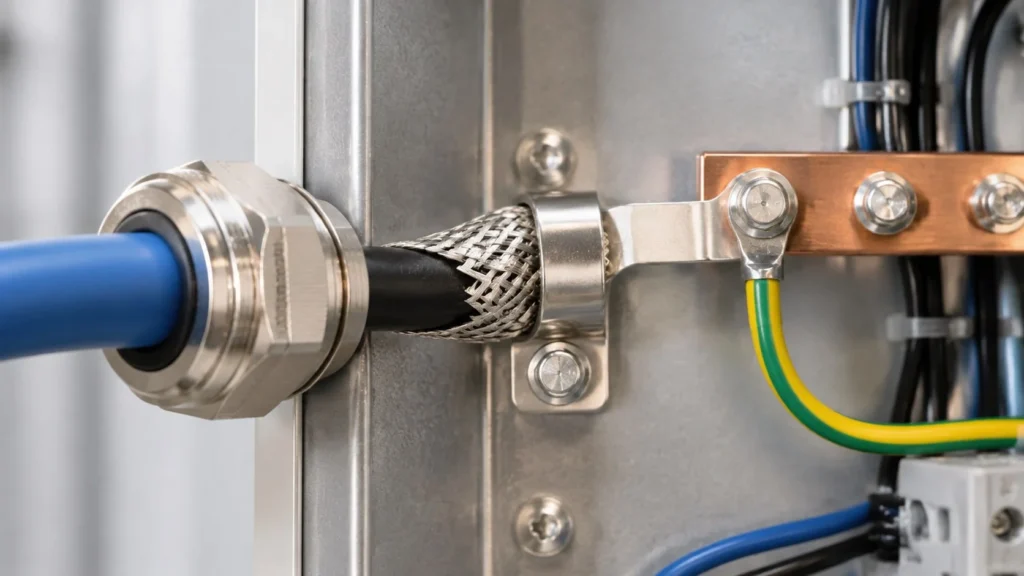
Bond the shield to the enclosure earth at the entry point, with a short connection — a pigtail of 20 mm is fine, a 300 mm wire is not.
Do not bond the shield at both ends unless the installation has an equipotential bonding system that keeps both ends at the same potential. Between two buildings, bonding both ends creates a circulating current that appears as noise and can be worse than no shield.
Do not connect the shield to the signal ground or to the 0 V terminal. The shield is a screen, not a reference conductor.
Bond the cabinets to each other with a dedicated conductor sized for the fault current, so the SPDs at both ends operate against the same reference.
The shield folded back over the sheath and clamped at the entry: one point of bonding, a short connection, and no shield current through the signal terminals.
24 V PLC I/O is a different circuit
A digital input is single-ended: the PLC reads the voltage between the input terminal and its 0 V rail. A surge that lifts the 0 V rail relative to the cabinet earth appears as a signal at every input at once, which is why a single event can take out several channels.
Two details matter for selection. First, the SPD must protect the 0 V conductor as well as the signal conductor — a device that only clamps the signal line has no return path for the common-mode current. Second, the device’s continuous current rating has to cover the load: a 24 V output driving a 0.5 A solenoid needs a device rated for that current, not a 100 mA signal device.
Inductive loads are a separate problem. A solenoid or contactor coil generates a inductive kick when it opens, and no surge SPD will absorb that repeatedly. Fit a freewheeling diode across a DC coil, or an RC network across an AC coil, close to the load.
Mistakes that cost channels
Fitting an Ethernet or PoE SPD on an RS485 pair. The connector looks similar; the clamping voltage and the data-rate characteristics are not.
Protecting the signal line but not the 0 V. Common-mode surges then have no path to earth except through the transceiver.
Star-wiring the bus and then adding protection to each branch, which multiplies the paths into the same port.
Bonding the shield at both ends between buildings and treating the resulting noise as a device fault.
Ignoring the output current rating when protecting a 24 V output that drives a coil.
Perguntas frequentes
Do I need surge protection on every RS485 node?
At every point where the cable enters an enclosure, yes. Nodes inside the same cabinet share one entry point and normally one device. Nodes in separate buildings or separate cabinets each need their own.
Will an RS485 SPD reduce the maximum cable length?
It adds a small series resistance and some capacitance, so in principle yes. In practice the effect is negligible at ordinary baud rates; it becomes relevant at high data rates or when the bus is already close to its limits.
Can I use one device for RS485 and 4-20 mA?
Only if the device is specified for both and the Uc suits both circuits. The clamping voltage and the series impedance requirements are different, and a device optimised for a 24 V analogue loop may not pass a high-baud-rate RS485 signal cleanly.
What is the right Uc for a 24 V PLC input?
Above the highest normal voltage on the circuit, which for a 24 V system with tolerance is typically 30 V or more. A device with a Uc of 30–60 V is the usual range for 24 V DC industrial circuits.
Does the SPD replace good wiring practice?
No. A bus with correct topology, one-point shield bonding and proper termination will survive events that destroy a poorly wired one with the same protection fitted.
A 4-20 mA loop or a 0-10 V signal line carries almost no energy, which is exactly why a surge matters there. The transmitter, the PLC analogue card or the drive input is built around a few milliamps and a handful of volts, and a surge that would be a minor event on a power […]
Um SPD que tenha falhado não é, automaticamente, um dispositivo defeituoso. A maioria dos dispositivos de proteção contra picos de tensão é concebida para ser sacrificável: absorvem a energia dos picos, perdem um pouco da sua capacidade de cada vez e, eventualmente, chegam a um ponto em que já não conseguem limitar picos de forma útil e têm de ser retirados de serviço. Pergunte-se por que razão […]
Se perguntarmos quando é que um SPD deve ser substituído, a maioria das respostas limita-se à janela de estado. Trata-se de um indicador, mas, por si só, é pouco fiável: mostra que um dispositivo atingiu o fim da sua vida útil, mas nunca que ainda se encontra em condições de funcionamento. Um SPD pode estar eletricamente esgotado, mesmo que a janela ainda […]