A 4-20 mA loop or a 0-10 V signal line carries almost no energy, which is exactly why a surge matters there. The transmitter, the PLC analogue card or the drive input is built around a few milliamps and a handful of volts, and a surge that would be a minor event on a power circuit is enough to destroy the input stage. Standard power SPDs are the wrong tool for the job: they clamp at voltages far above what a signal input can survive, and their connection method does not suit a two-wire loop.
Signal surge protection for analogue loops works on a different set of rules. The device has to clamp well below the input’s withstand voltage, pass the signal without measurable distortion, and add so little series resistance that the loop still has enough compliance to drive its load.
Why a power SPD cannot protect a signal loop
Three differences decide it:
Property
Power SPD
Signal SPD for 4-20 mA / 0-10 V
Maximum continuous voltage (Uc)
275 V AC, 1000 V DC and above
Typically 30 V DC to 60 V DC for a 24 V loop
Clamping voltage (Up)
Kilovolts
A few tens of volts, below the I/O card withstand
Ligação
Parallel across a power circuit
In series with the loop, through a protected feed-through
A power SPD installed on a 24 V analogue loop will simply never conduct at a level the loop cares about, and its clamping voltage is an order of magnitude above the destruction threshold of the input. The signal SPD sits in series with the pair, passes the loop current through, and diverts the surge to earth through its clamping element.
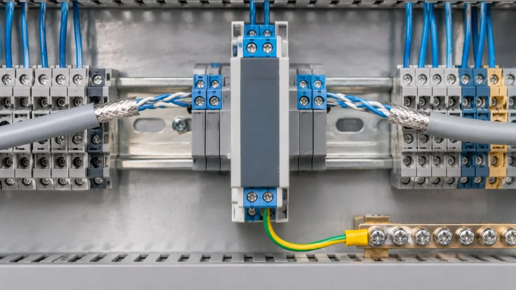
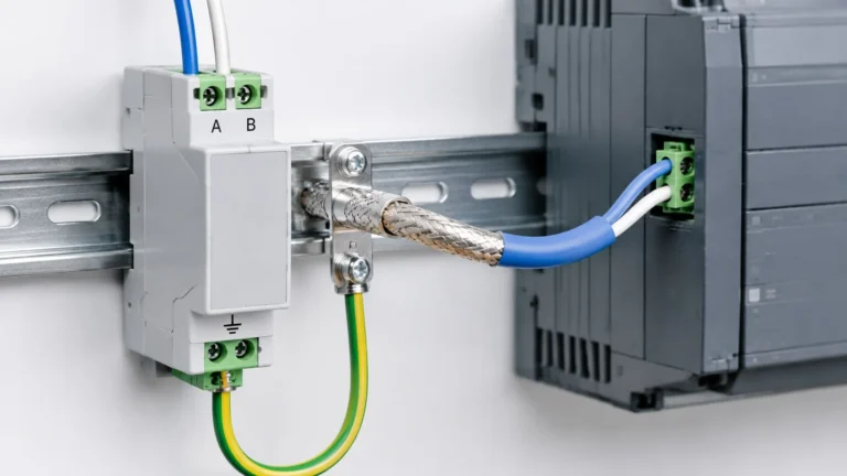
A series-connected signal SPD: the loop passes through the protected feed-through, and the earth conductor to the PE bar is kept short.
The four numbers that decide the device
Uc, maximum continuous operating voltage. Must be above the highest voltage the loop can see in normal operation, with margin. A 24 V DC loop with a 10 percent tolerance needs at least 30 V; a 0-10 V signal inside a drive cabinet may see higher voltages during a fault. Uc below the normal loop voltage means the device conducts continuously and fails.
In, nominal discharge current. Typically 5 kA or 10 kA with an 8/20 µs waveform for instrument loops. Higher values exist but are rarely needed inside a panel; at a field device on a long outdoor run, the higher figure is easier to justify.
Up, voltage protection level. The only number that matters to the electronics, and it has to be compared with the input card’s withstand specification, not with the loop’s normal voltage. If the card datasheet does not state a surge withstand, the safe assumption is that it is low.
Series resistance. Every series-connected SPD adds resistance to the loop. A 4-20 mA transmitter has a maximum loop resistance it can drive — usually stated as a supply voltage versus load resistance graph. The SPD’s resistance, the cable resistance and the receiver’s input resistance all add up, and if the total exceeds the transmitter’s capability the loop reads low or drops out at the top of its range.
The 4-20 mA loop has a budget, and the SPD spends from it
A two-wire transmitter regulates its current to represent the measurement, and it can only do that while the total loop resistance keeps the supply voltage within its operating window. Adding a series device consumes part of that budget.
Worked example, with illustrative values: a 24 V supply, a transmitter that needs at least 12 V across itself, and a 250 Ω receiving resistor. The voltage available for the rest of the loop is 24 − 12 = 12 V, and at 20 mA the 250 Ω resistor drops 5 V. That leaves 7 V for cable and any series devices, which corresponds to 350 Ω at 20 mA. An SPD contributing a few ohms is negligible; one contributing tens of ohms per wire is not, especially on a long run.
The point is not the specific numbers, which vary by transmitter, but the method: add the SPD’s resistance to the loop calculation before ordering, and check the transmitter’s load graph rather than assuming headroom.
Where to install it
Protection has to be at the boundary where the surge enters, and there can be two such boundaries.
At the field device. Protects the transmitter from surges induced on the long cable run. Common on outdoor installations, tank farms and anywhere the instrument is remote from the panel.
At the panel entry. Protects the analogue card from what arrives on the cable. This is the minimum, and it is the one that is most often missing.
Both ends. Used when the field device and the panel are in separate buildings or separated by a long run, where a ground potential difference can develop between the two earth references.
The two devices must be coordinated. A signal SPD at each end with no consideration of the cable length between them can leave the downstream device doing nothing, because the upstream one has already clamped the surge to a level the downstream one never sees. Where the run is long this is rarely an issue; where the two devices are close together, follow the manufacturer’s coordination guidance.
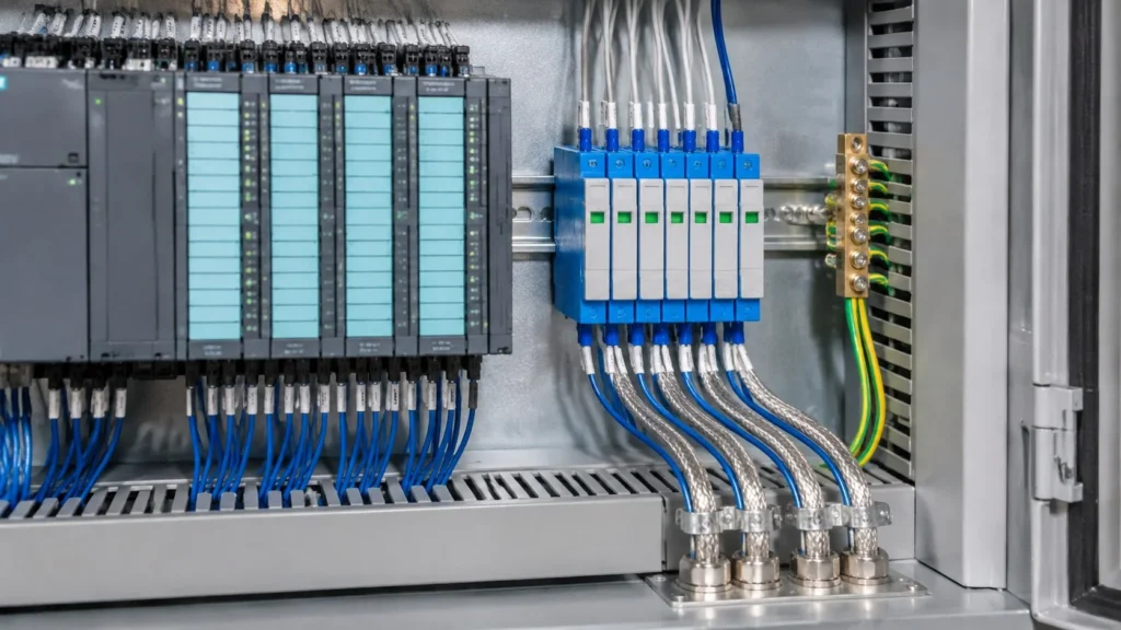
Protection at the panel entry, beside the analogue cards: the shield is clamped where the cable enters, not landed on the signal terminals.
Grounding and shielding decide whether it works
Most damage to analogue inputs is common-mode: the surge raises the potential of the whole cable relative to the panel earth, and the input sees the difference. That means the SPD’s earth connection is part of the signal path, not an afterthought.
Connect the SPD earth to the same earth bar as the analogue card, with a short, direct conductor. A long earth lead adds inductive voltage on top of Up.
Ground the cable shield at one end only, normally the panel end, unless the installation uses a equipotential bonding system that makes both ends legitimate. Grounding both ends of a shield between buildings creates a circulating current that shows up as noise on the measurement.
Bond the cable tray and the enclosure so that the shield, the tray and the panel earth are at the same potential before the SPD operates.
0-10 V is not the same problem as 4-20 mA
A voltage signal is read by a high-impedance input, so a small series resistance produces almost no error in normal operation. The failure mode is different: the input is sensitive to any leakage path to earth, and a signal SPD with a low insulation resistance or a contaminated terminal block will drag the signal down. For 0-10 V loops, check the device’s insulation resistance and keep the terminals clean and dry rather than worrying about series resistance.
Also check Uc carefully. A 0-10 V signal may sit inside a cabinet where a 24 V control supply is also present, and a device with a 15 V Uc would conduct continuously.
Mistakes worth avoiding
Using a power SPD on an analogue loop and assuming it protects the card because it is “surge protection”.
Choosing Uc from the nominal signal — 10 V — without accounting for the 24 V supply in the same pair.
Ignoring series resistance until the loop reads low at the top of its range.
Grounding the shield at both ends between buildings and calling the resulting noise a sensor problem.
Fitting protection at the panel only when the field device is 200 m away and is the more expensive item.
Perguntas frequentes
Does a 4-20 mA loop need surge protection?
If the cable leaves the building, runs more than a few tens of metres, or connects equipment on different earth references, yes. The input card and the transmitter are both low-energy devices with little tolerance for overvoltage.
Can I use one signal SPD for two loops?
Only if the device is designed for two channels. Sharing a single-channel device between two loops defeats the isolation between them and can create a path between signals that should be independent.
Will a signal SPD affect the 4-20 mA reading?
Not if the series resistance is small relative to the loop budget. It becomes visible when the transmitter is already near its maximum load resistance, which is why the loop calculation has to include the device.
What standard applies to signal SPDs?
IEC 61643-21 covers surge protective devices connected to telecommunications and signalling networks. Ask for the test classification rather than relying on a generic “surge protection” description.
Do I need protection on the 24 V supply as well?
Yes, and it is a separate device. A 24 V DC power SPD protects the supply feeding the loop; the signal SPD protects the measurement pair. They are not interchangeable.
RS485 and 24 V PLC I/O are the two interfaces that fail most often in industrial installations, and they fail for a reason that has nothing to do with the data rate. Both run on long cables between cabinets that sit on different earth references. When lightning or a switching event raises the potential of […]
Um SPD que tenha falhado não é, automaticamente, um dispositivo defeituoso. A maioria dos dispositivos de proteção contra picos de tensão é concebida para ser sacrificável: absorvem a energia dos picos, perdem um pouco da sua capacidade de cada vez e, eventualmente, chegam a um ponto em que já não conseguem limitar picos de forma útil e têm de ser retirados de serviço. Pergunte-se por que razão […]
Se perguntarmos quando é que um SPD deve ser substituído, a maioria das respostas limita-se à janela de estado. Trata-se de um indicador, mas, por si só, é pouco fiável: mostra que um dispositivo atingiu o fim da sua vida útil, mas nunca que ainda se encontra em condições de funcionamento. Um SPD pode estar eletricamente esgotado, mesmo que a janela ainda […]