Type 2 DC Surge Suppressor Selection for Solar, BESS and DC Panels
Publicado: Autor: info@cngdfl.com
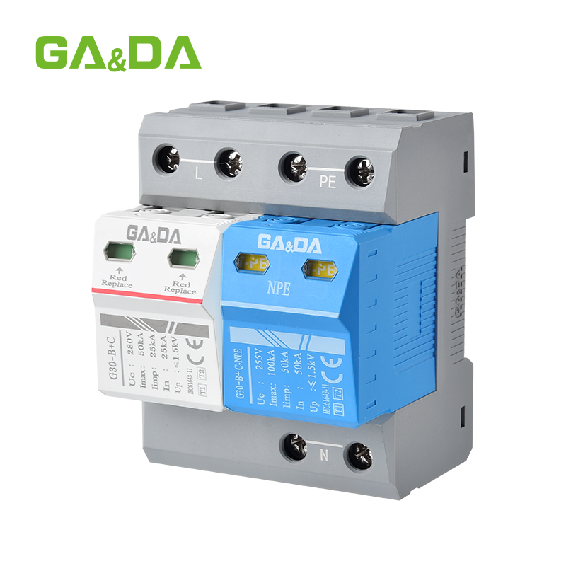
If you’re looking at DC Dispositivos de proteção contra picos de tensão, you’re probably responsible for gear that absolutely cannot go down: solar PV fields, battery energy storage systems, telecom racks, industrial DC panels, or even EV fast chargers. In all those places, a Type 2 DC surge suppressor is the small DIN‑rail box standing between your investment and an expensive “pop” you hear during a storm or switching event.
In this article I’ll walk you through how to choose, where to use, and how to connect the right device, using concrete examples like Type 2 DC surge suppressor 40 kA In, Type 2 DC surge protection device 1500 V DC, e Type 2 DC surge suppressor 1000 V DC Uc. We’ll also touch on standards such as IEC 61643‑31 Type 2 DC SPD and practical variants like DIN‑rail Type 2 DC SPD with remote alarm. And yes, I’ll keep it as down‑to‑earth as possible—because you’ve got projects to deliver, not standards to memorize.
Let’s start with the basics, but quickly. A Type 2 DC surge suppressor (or Type 2 DC SPD) is a surge protective device specifically designed for DC circuits, tested with an 8/20 µs surge waveform and intended to handle indirect lightning strikes and switching surges in the distribution level of your system.
It is not there to take a direct hit from lightning; instead, it clips and diverts the residual surge energy that reaches your DC side after upstream protection and the installation’s earthing system have done their job. That’s why you see it everywhere in the middle of the system: in the PV combiner box, in the BESS container, inside the telecom 48 V DC rack, or in an industrial DC control panel.
Put in one sentence: the Type 2 DC surge suppressor limits overvoltage to a level your inverter, battery management system, telecom rectifier, PLC, or EV charger electronics can tolerate.
Main application scenarios
Solar PV: inside the combiner box
In a solar plant, the classic device is a Type 2 DC SPD for solar PV combiner box. Here it’s mounted on a DIN rail right after the string inputs and DC fuses, clamping surges before they reach the DC bus and the inverter’s DC input.
For most medium and large PV systems, engineers often specify a Type 2 DC surge suppressor 40 kA In as a good balance between protection level and cost, especially on 1000 V or 1500 V DC strings. When the plant is built with long DC cable runs in open fields, going for a Type 2 DC surge protection device 1500 V DC is standard practice to match modern high‑voltage strings.
BESS: protecting high‑value batteries
In battery storage, you typically see a Type 2 DC surge suppressor for BESS 1500 V DC at the interface between the battery rack and the DC bus or converter. The surge suppressor protects battery racks and power conversion systems against transients caused by switching operations, nearby lightning, or grid‑side disturbances coupling into the DC side.
Because BESS containers are often packed with electronics, fire‑safety and monitoring matter. So a spec line here often reads something like: “DIN‑rail Type 2 DC SPD with remote alarm, 1500 V DC Uc, 40 kA In, with thermal disconnector,” giving you both robust surge capacity and remote status monitoring.
Telecom DC power systems (48 V DC)
In telecom applications, power systems often run at 48 V DC, which is low voltage but mission‑critical. A Type 2 DC SPD for telecom 48 V DC is usually placed near the rectifier outputs or distribution panels that feed BTS equipment, radio units, and network switches.
Here the priorities are compact size, low residual voltage, and high reliability. You still want a DIN‑rail device, but sized for lower system voltage: something like a 48–75 V DC Uc rating, with decent surge handling, and ideally remote signalling so the NOC can see when a surge module has failed.
Industrial DC control panels
In factories, water plants, and process lines, you’ll often find PLCs, sensors, actuators, and drives powered from a DC bus at 24 V, 48 V or higher. To keep these control systems stable during switching operations, motors starting, or nearby lightning, you use a Type 2 DC surge suppressor for industrial DC control panel.
This device typically sits on the same DIN rail as DC power supplies, DC‑DC converters, and I/O modules, clamping surges before they can jump into delicate PLC inputs or fieldbus modules. Here again, a DIN‑rail Type 2 DC SPD with remote alarm is popular because maintenance teams can see the SPD state directly from the SCADA or DCS.
EV charging DC side
Finally, high‑power DC fast chargers are another growing application. On the DC output side feeding the vehicle, a Type 2 DC surge suppressor for EV charging DC side is used to protect the DC link, control electronics, and sometimes the communication circuits between charger and EV.
This environment can be rough: repetitive high currents, outdoor installation, and a mix of AC and DC disturbances. That’s why many EV charging designs specify a robust, high‑voltage Type 2 DC surge protection device 1500 V DC or whatever maximum DC output the charger needs, ensuring enough headroom during load changes and surges.
Learn how to pick, wire, and spec the right AC Surge Protective Device for industrial and commercial projects.
Now let’s match your keywords to the most important parameters you should look at when selecting a SPD.
Uc – maximum continuous operating voltage
Uc must always be equal to or higher than your system’s maximum DC voltage.
For modern PV strings up to 1000 V, you will commonly use a Type 2 DC surge suppressor 1000 V DC Uc, which is designed to stay stable at that continuous voltage level.
For newer, higher‑voltage arrays and BESS systems, a Type 2 DC surge protection device 1500 V DC is used so that even at temperature‑related voltage rises and no‑load conditions, the SPD will not enter conduction prematurely.
So when you’re choosing between 1000 V and 1500 V models, you’re really just matching the Uc value to your system, then checking the rest of the SPD ratings.
In – nominal discharge current (and why 40 kA matters)
O Em rating tells you how much surge current (with the standard 8/20 µs waveform) the SPD is designed to handle repeatedly.
In many PV, BESS, and industrial applications, a Type 2 DC surge suppressor 40 kA In is a sweet spot: high enough to survive serious surges over its life, but not so over‑engineered that it kills your budget. For lighter duty or more protected environments, 20 kA In may be enough, but 40 kA In is a very common reference level for professional B2B projects.
Installation format and monitoring
You specified DIN‑rail Type 2 DC SPD with remote alarm, which is exactly what most engineers end up asking for when they realize the maintenance advantages.
DIN‑rail mounting lets you drop the SPD into a combiner box, BESS cabinet, telecom rack, or industrial control panel with standard tooling. The remote alarm (often a change‑over contact) allows the system controller or SCADA to receive a signal when the SPD module has reached end‑of‑life or tripped, so you’re not relying only on someone checking a little red window on site.
Standards and compliance
To make sure the device does what the label claims, it should be tested and certified under the right standards. For DC SPDs, the reference is IEC 61643‑31 Type 2 DC SPD, which defines test procedures, surge waveforms, performance levels, and marking for surge protective devices in DC applications.
When you see “Type 2 DC surge suppressor” on a datasheet, you want that to be backed by compliance to IEC 61643‑31 (or the corresponding EN adoption). This is especially important for EPC contractors working on utility‑scale solar farms, BESS installations, and critical infrastructure like telecom and EV charging, where insurance and grid‑code requirements depend on recognized standards.
Practical selection examples
To make this even more concrete, let’s walk through three short examples.
Example 1: 1000 V solar rooftop with combiner box
You’re designing a 500 kW rooftop PV system with 1000 V DC strings and several roof‑mounted combiner boxes. Here you’d choose:
Uc: 1000 V DC → Type 2 DC surge suppressor 1000 V DC Uc
Candidatura: Type 2 DC SPD for solar PV combiner box
Em: to be safe, Type 2 DC surge suppressor 40 kA In per pole
Montagem: DIN‑rail Type 2 DC SPD with remote alarm so that faults are visible from the main monitoring system
Result: robust, standardized protection across all combiner boxes.
Example 2: 1500 V BESS container
You’re specifying protection for a containerized battery system with a 1500 V DC bus. Your shortlist will probably say:
Use a Type 2 DC surge suppressor for BESS 1500 V DC at each connection point between racks and bus
Choose Type 2 DC surge protection device 1500 V DC compliant with IEC 61643‑31 Type 2 DC SPD
Request remote alarm capability for integration into the energy‑management system
Now you’ve aligned device voltage, type, and standard in one shot.
Example 3: Mixed site with telecom, industrial DC, and EV chargers
On a campus or smart‑city project, you may have:
Small telecom shelters needing a Type 2 DC SPD for telecom 48 V DC
Process control panels needing a Type 2 DC surge suppressor for industrial DC control panel
DC fast chargers requiring a Type 2 DC surge suppressor for EV charging DC side
You can standardize the vendor and platform by selecting a product family that covers all these variants, each with appropriate Uc and In ratings, but with the same DIN‑rail footprint and remote alarm interface. That makes life easier for both purchasing and maintenance.
A container is not one DC circuit. Surge energy reaches it at several boundaries, each with a different source impedance and a different piece of electronics downstream that has to survive. Treating the whole container as a single protected node is the most common reason a BESS surge protector is fitted, passes inspection, and still lets a BMS input card fail.
The boundaries where surge energy enters
Rack to DC bus. The longest cable run in the system, and the one that picks up the most induced surge. Energy couples into the loop formed by the positive and negative conductors, so the length and the routing matter more than the device rating.
DC bus to PCS. The bus is already partially protected by the rack devices, but the PCS input electronics are the most sensitive load on the DC side and usually have the lowest withstand voltage.
Auxiliary and control supply. The 24 V or 48 V rail feeding the BMS, contactors and relays is a separate circuit with a separate failure mode. A power SPD on the 1500 V bus does nothing for it.
Communication lines. RS485 or Ethernet between BMS, PCS and the site controller needs a signal SPD, not a power device with a low Uc. The two are not interchangeable even when the voltage figure looks close.
Which type applies on a DC bus
IEC 61643-31 keeps the same type numbering as the AC standard, and it means the same thing. Type 1 is tested with a partial lightning current waveform of 10/350 µs; Type 2 is tested with an 8/20 µs surge. The type describes the test the device passed, not the size of the box.
In practice: if the DC bus leaves the container and runs to a separate PCS skid, or along a row of racks in the open, the entry point wants Type 1. Inside the container, at the rack output, Type 2 is what coordinates with it. A Type 2 device alone at the entry leaves the cable between entry and rack exposed to the partial lightning current that the 10/350 waveform represents, and that is precisely where an unshielded DC bus is most likely to pick it up.
Type and Up are separate decisions. A Type 1 device with a high Up can still protect nothing if the BMS input is rated lower than that Up, because the clamping level has to sit below the withstand of the weakest device on the bus. Read the two numbers together, and check them against the PCS or BMS manual rather than against the SPD datasheet alone. The definitions of Iimp, In, Imax e Up are set out separately if the labels are still unclear.
Coordinating the SPD with the DC breaker or fuse
Every SPD needs a backup device in front of it, sized so that a short circuit inside the SPD is cleared before the housing ruptures, while a normal surge does not trip it. That rating comes from the SPD datasheet, not from the circuit current. Sizing it to the cable instead is a common error, and the result is either a device that trips on every surge or one that cannot clear a failed cartridge. The selection logic is the same as for AC, and the Fusível ou disjuntor de reserva do SPD guide walks through it.
Two physical rules decide whether the device works at all:
Lead length. The connecting leads between the SPD and the busbar should be as short as the layout allows. Surge current through a long lead adds an inductive voltage rise on top of Up, so a device specified at 3.9 kV can present well over 4 kV to the equipment it is supposed to protect.
Decoupling. Two SPDs in series need an inductive length between them, typically at least 10 m of cable, or a dedicated decoupling element. Without that, the downstream device sees only the residual of the upstream one and never operates.
A worked container layout
The table below is a typical arrangement for a 1500 V container, not a specification. Confirm every value against the device datasheet and the PCS or BMS input withstand before ordering.
Boundary
Dispositivo
Ucpv
Em
Para cima
Backup protection
DC bus entry from rack strings
Type 1+2 DC SPD
1500 V or above
25 kA
4 kV or below
125 A gPV fuse
Rack output
Type 2 DC SPD
1500 V or above
20 kA
3.9 kV or below
63 A gPV fuse
PCS DC input
Type 2 DC SPD
1500 V or above
20 kA
2.5 kV or below
Per PCS manual
48 V auxiliary rail
Type 2 DC SPD
75 V or above
10 kA
1.5 kV or below
16 A gG fuse
RS485 or Ethernet
Signal SPD
Per line voltage
5 kA, 8/20
Clamped at the port
Nenhum
On a 1000 V system the layer count does not change, only Ucpv. Devices rated for 1500 V work on a 1000 V bus, but they clamp at a higher level, which costs protection margin for electronics sized around the lower voltage. The comparison of 1000 V and 1500 V DC SPDs covers where the extra margin is worth paying for.
Three architecture mistakes
One device for the whole container. A single SPD at the entry protects the bus, not the electronics at the far end of a 30 m rack row. The inductive rise along that run is exactly what the second layer exists to absorb.
Bonding that adds to Up. The SPD earth lead has to reach the same earth bar as the equipment, as directly as possible. A long lead to a remote earth point adds inductive voltage on top of the clamping level, and the equipment sees the sum. Every extra metre of bonding costs protection margin, and it is invisible on a single-line diagram.
Backup protection chosen for the breaker, not the SPD. The fuse or breaker ahead of the SPD exists to protect the SPD. If it is selected to match the outgoing circuit instead, the coordination is wrong even though the numbers look reasonable on paper.
Perguntas frequentes
Do I always need 1500 V DC models?
No. You choose between Type 2 DC surge suppressor 1000 V DC Uc e Type 2 DC surge protection device 1500 V DC based on your actual system voltage. Oversizing Uc too far can compromise protection level, so match the SPD to your design voltage with reasonable headroom.
When is 40 kA In worth paying for?
If you’re protecting large PV fields, BESS, or outdoor EV charging and industrial DC panels, a Type 2 DC surge suppressor 40 kA In gives you a strong safety margin against repeated surges. For very small or well‑shielded systems, 20 kA might be enough, but 40 kA is a common “no‑regrets” choice.
Is the remote alarm really necessary?
For single small systems, you might skip it. But for anything spread out—solar farms, telecom networks, BESS sites—a DIN‑rail Type 2 DC SPD with remote alarm saves a lot of manual inspection time. Your control room can see when a module fails instead of waiting for a field visit.
Why is IEC 61643‑31 important?
Because IEC 61643‑31 Type 2 DC SPD certification tells you the device has been tested for DC surge duty using standardized procedures. That makes it easier to justify your design to consultants, insurers, and clients, and reduces the risk of “mystery” failures.
RS485 and 24 V PLC I/O are the two interfaces that fail most often in industrial installations, and they fail for a reason that has nothing to do with the data rate. Both run on long cables between cabinets that sit on different earth references. When lightning or a switching event raises the potential of […]
A 4-20 mA loop or a 0-10 V signal line carries almost no energy, which is exactly why a surge matters there. The transmitter, the PLC analogue card or the drive input is built around a few milliamps and a handful of volts, and a surge that would be a minor event on a power […]
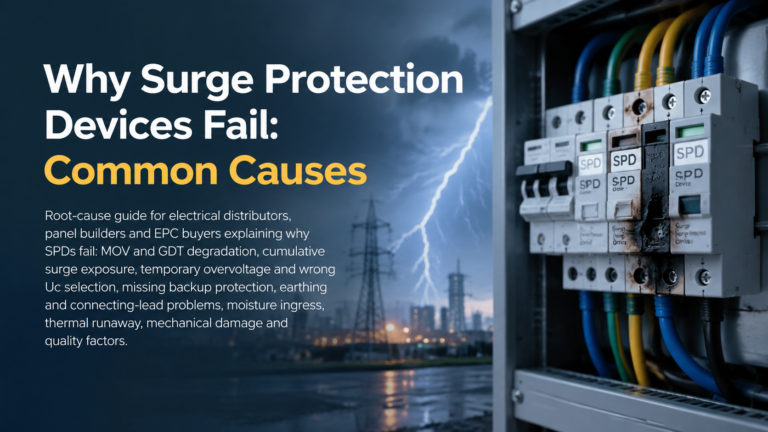
Um SPD que tenha falhado não é, automaticamente, um dispositivo defeituoso. A maioria dos dispositivos de proteção contra picos de tensão é concebida para ser sacrificável: absorvem a energia dos picos, perdem um pouco da sua capacidade de cada vez e, eventualmente, chegam a um ponto em que já não conseguem limitar picos de forma útil e têm de ser retirados de serviço. Pergunte-se por que razão […]