Engineers who understand fuse breaking capacity and voltage ratings can design safer, more reliable low‑voltage and PV systems. In any power distribution or PV combiner box, the fuse breaking capacity defines the maximum fault current the fuse can safely interrupt at its rated voltage without exploding or failing dangerously. In practical panel layouts this often involves pairing high‑capacity links such as the NT00 160A 250A 400A AC fuse link with an appropriate AC fuse base for low voltage fuse links.
This guide explains what fuse breaking capacity really means, how it interacts with voltage ratings, and how to select the right combination for feeders, PV strings, and battery circuits. By the end, fuse breaking capacity will be more than just a datasheet number; it will be a practical design parameter for coordinating protection with system fault levels and insulation limits.
Why fuse breaking capacity and voltage ratings matter
In every system short‑circuit study, fuse breaking capacity is a critical boundary between safe interruption and catastrophic failure. If the available fault current at a given point exceeds the fuse breaking capacity, the device may not clear correctly, risking arcing, enclosure damage, or even fire. That is why standards and manufacturers emphasize that fuse breaking capacity must always be equal to or higher than the maximum prospective short‑circuit current at the installation point.
Voltage ratings matter just as much. A fuse can only achieve its specified breaking capacity if the system voltage does not exceed the rated value. When fuse breaking capacity is quoted on a datasheet, it assumes a particular voltage and power factor; operating above that voltage may allow the arc to persist even after the element has melted. Engineers therefore have to treat fuse breaking capacity and voltage ratings as a linked pair when selecting protection devices for AC feeders or DC PV strings.
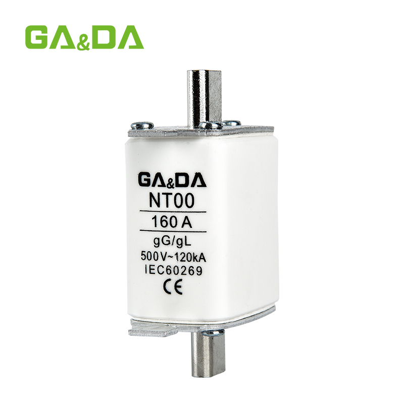
Product illustration – high‑capacity low‑voltage feeder fuses A typical example of combining fuse breaking capacity and voltage ratings in low‑voltage feeders is the NT00 160A 250A 400A AC fuse link installed in an Alternating Current Fuse Base, providing high breaking capacity at standard AC distribution voltages.
(Insert NT00 + AC fuse base image here and link to URLs.)
Fuse breaking capacity and voltage ratings fundamentals
To use fuse breaking capacity and voltage ratings correctly, it helps to break the concept into two questions: how much current the fuse can interrupt, and at what maximum system voltage. Both answers are tightly defined by standards such as IEC 60269 for low‑voltage fuses, which specify the test conditions and performance criteria for safe operation. For engineers, these numbers on the label translate directly into limits for where the fuse can be installed.
In simple terms, fuse breaking capacity is like the fuse’s personal short‑circuit rating, while the voltage rating defines the electrical environment in which that rating is valid. If either parameter is exceeded, the assumptions behind the tested fuse breaking capacity no longer hold. That is why serious coordination work always treats fuse breaking capacity and voltage ratings together rather than as separate checkboxes.
Defining fuse breaking capacity in practice
In practice, fuse breaking capacity (often called interrupting rating) is the highest prospective short‑circuit current that the fuse can safely interrupt at its rated voltage. During testing, the fuse is subjected to that fault current under standardized conditions; to pass, it must clear the fault without violent rupture or allowing sustained arcing. When you see a breaking capacity of, for example, 80 kA at 400 V AC, this is a guarantee that the fuse has been verified to handle that worst‑case scenario.
For engineers, the key is to compare this fuse breaking capacity with the calculated or utility‑provided short‑circuit current at the point of installation. If the fault level is higher than the fuse breaking capacity, the fuse cannot be used there, or it must be backed up by another device with higher interrupting capability. This is especially important near transformers or generators where prospective fault currents are highest.
How voltage ratings relate to fuse breaking capacity
Voltage ratings tell you the maximum system voltage at which the fuse can safely perform to its specified breaking capacity. A fuse rated 500 V AC has had its fuse breaking capacity tested at that voltage; applying it at 690 V AC would go beyond the validated conditions. The higher voltage can sustain longer arcs and greater energy release, so the original fuse breaking capacity figure would no longer be valid.
DC applications introduce additional challenges because DC arcs do not benefit from natural current zero crossings. For this reason, DC voltage ratings are often lower than their AC counterparts for a given physical fuse design, or require special DC‑optimized construction. When engineers size fuses for PV strings or battery buses, they must ensure that both the DC voltage rating and fuse breaking capacity meet or exceed the worst‑case operating conditions, not just the nominal values.
Product illustration – DC string fuses with coordinated voltage and breaking capacity In PV string protection, devices like the GD‑10PV 10×38 mm Direct Current Fuse Link 32A are specifically rated for high‑voltage DC, with fuse breaking capacity and voltage ratings aligned to typical 1000 V or 1500 V PV strings. Matching these fuses with a GDPV‑32 DC Fuse Base 1P 2P ensures the mechanical insulation supports the same ratings. (Insert GD‑10PV + GDPV‑32 image here and link to URLs.)
How to select fuse breaking capacity and voltage ratings
Real‑world selection of fuse breaking capacity and voltage ratings always starts with understanding the system. The engineer must know the nominal system voltage, the maximum possible voltage under abnormal conditions, and the prospective short‑circuit current at the fuse location. These quantities are usually obtained from short‑circuit studies, utility data, or conservative calculations based on transformer and cable parameters. Fuse breaking capacity and voltage ratings are then chosen to exceed these values with appropriate margins.
Another critical aspect is to consider the coordination between upstream and downstream protective devices. Fuse breaking capacity defines the top limit of what the fuse itself can handle, but selectivity requires that this fuse also behaves correctly relative to breakers or other fuses in the system. The chosen voltage rating must be compatible with the insulation levels of the switchgear and the earthing system used, particularly in TN, TT, or IT networks.
Step-by-step fuse breaking capacity selection
A practical workflow for selecting fuse breaking capacity and voltage ratings looks like this:
Determine system voltage and configuration Identify whether the system is, for example, 230/400 V AC three‑phase, 690 V AC, 600 V DC, 1000 V DC PV, or another value. Confirm earthing system and insulation requirements.
Calculate or obtain prospective short‑circuit current Use short‑circuit calculations or utility data to find the maximum fault current at the installation point. For PV and battery systems, consider worst‑case contributions from strings, inverters, and parallel sources.
Choose a voltage rating equal to or above system voltage Select fuses whose rated voltage meets or exceeds the highest possible system voltage at that location, including tolerances and transient overvoltages allowed by standards.
Select fuse breaking capacity above the fault level Ensure the fuse breaking capacity is greater than or equal to the calculated short‑circuit current, ideally with a margin to account for calculation uncertainties or system changes.
Verify utilization category and application Confirm that the fuse type (gG, aM, gPV, etc.) matches the application, so that fuse breaking capacity and voltage ratings are applied in the correct operating context.
Coordinating fuse breaking capacity with system fault levels
In multi‑level distribution systems, engineers must coordinate fuse breaking capacity with fault levels at each stage. Near the transformer, fault currents are highest, so fuses and switchgear require the greatest breaking capacity. Further downstream, fault currents are reduced by cable impedance and upstream devices, so smaller breaking capacities may be acceptable. The coordination challenge is to ensure that each level can safely interrupt any fault that can realistically occur at its location.
Fuse breaking capacity also interacts with back‑up protection. In some cases, a downstream device has a lower breaking capacity than the system fault level, but is backed up by an upstream device with higher capacity. This concept is recognized in fuse and breaker standards; however, it demands careful verification that the upstream fuse or breaker will operate in time to protect the lower‑rated device. Getting this wrong can leave a weak link exposed to fault currents beyond its fuse breaking capacity, undermining the entire protection scheme.
Product illustration – modular fuse switch disconnectors in coordinated systems In coordinated low‑voltage feeders, engineers often use devices such as the GDHR18‑160 Fuse Switch Disconnector 1P 2P 3P, which combine appropriately rated fuse breaking capacity and voltage ratings with safe load‑break and isolation functions. (Insert GDHR18‑160 image here and link to URL.)
Applications that stress fuse breaking capacity and voltage ratings
Certain applications place especially high demands on fuse breaking capacity and voltage ratings. Transformers and main distribution boards near the service entrance can experience very high fault currents, requiring fuses with substantial breaking capacities and robust mechanical construction. In such cases, engineers typically choose NH or similar high‑capacity fuses designed to meet the highest short‑circuit levels seen in the system.
PV and battery energy storage systems stress voltage ratings as well as fuse breaking capacity. Long strings and high‑energy battery racks can maintain high DC voltages under fault conditions, making arc extinction more challenging. Here, gPV fuses with clearly defined DC voltage ratings and verified DC fuse breaking capacities are essential. Designers must also ensure that combiner boxes and enclosures have insulation performance compatible with the same voltage and energy levels.
Practical tips to avoid mistakes with fuse breaking capacity
Even experienced engineers can make avoidable mistakes with fuse breaking capacity and voltage ratings when projects move fast or documentation is incomplete. A common error is assuming that any fuse of the right physical size is suitable for replacement, without checking whether the original had a higher breaking capacity or different voltage rating. Over time this can degrade the safety margin of the installation.
Another common issue is mixing AC and DC applications. Using an AC‑only fuse in a high‑voltage DC string is a serious misapplication, because the DC arc may not extinguish at the expected fuse breaking capacity. Always verify that both fuse breaking capacity and voltage ratings explicitly cover the intended AC or DC system, and that the utilization category matches the type of load and fault profile.
Good documentation helps. Panel schedules and single‑line diagrams should record both fuse breaking capacity and voltage ratings for each protective device. This makes future changes or maintenance safer, ensuring that replacements or modifications do not inadvertently lower the protective performance that the original designer intended.
FAQ – understanding fuse breaking capacity and voltage ratings
Q1. Is it acceptable to use a fuse with a higher breaking capacity than required? Yes. Using a fuse with a fuse breaking capacity higher than the calculated fault current is generally acceptable and can provide extra safety margin, as long as the voltage rating and utilization category are appropriate and the time‑current characteristics still provide the desired protection.
Q2. Can a fuse rated for a higher voltage be used on a lower‑voltage system? Often yes, but only if the utilization category and other characteristics are suitable. For example, a 690 V AC fuse with adequate fuse breaking capacity can normally be used on a 400 V AC system, but engineers must check manufacturer guidance to ensure correct operation and coordination.
Q3. Why do DC fuses often have different voltage ratings than AC fuses of the same size? Because DC arcs are harder to extinguish and do not benefit from natural current zero crossings. DC fuses therefore need specific internal designs and are tested separately; their fuse breaking capacity and voltage ratings are not interchangeable with those of AC‑only fuses.
Q4. What happens if system fault current exceeds fuse breaking capacity? If a fault current higher than the fuse breaking capacity occurs, the fuse may not be able to interrupt the fault safely. This can result in uncontrolled arcing, violent rupture of the fuse body, or damage to the enclosure, which is why correct coordination is critical.
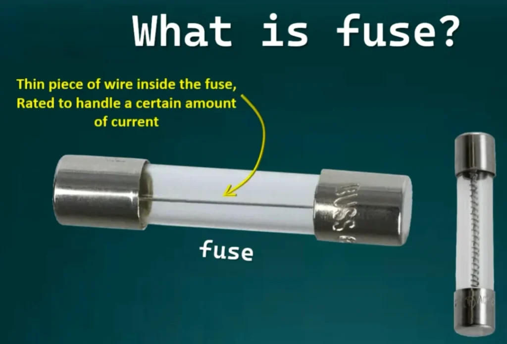
TABLE OF CONTENTS Understanding what is a fuse is fundamental for anyone designing, installing, or maintaining electrical and photovoltaic systems. When engineers ask “what is a fuse,” they are talking about a deliberately weak link in the circuit that sacrifices itself to protect cables, devices, and people from dangerous overcurrent. In low‑voltage panels this often […]
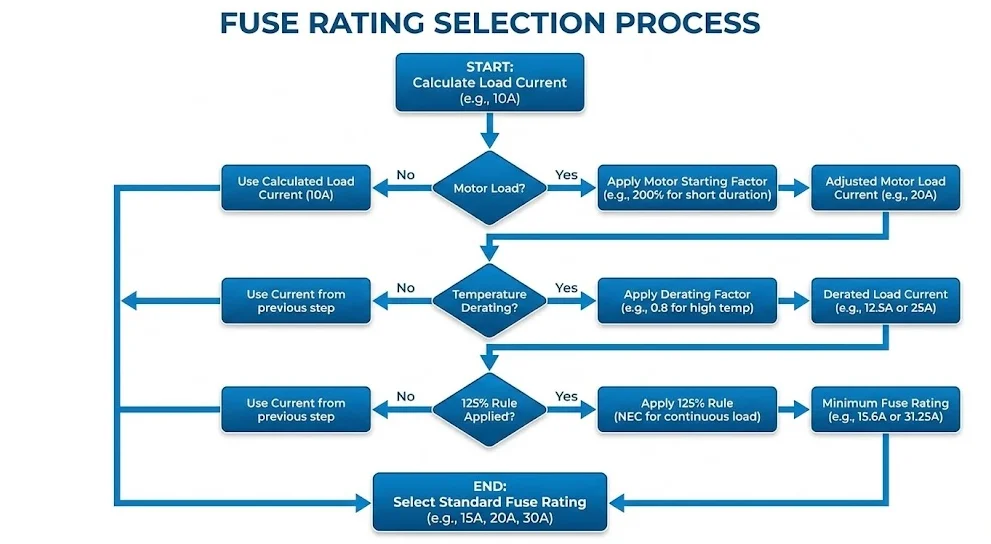
TABLE OF CONTENTS Introduction to Fuse Rating Selection Selecting the right fuse rating for electrical circuits is one of the most critical decisions in electrical system design and installation. The fuse rating determines how much current can flow safely through a circuit before the fuse operates to protect against overcurrent conditions. Choosing the correct fuse […]
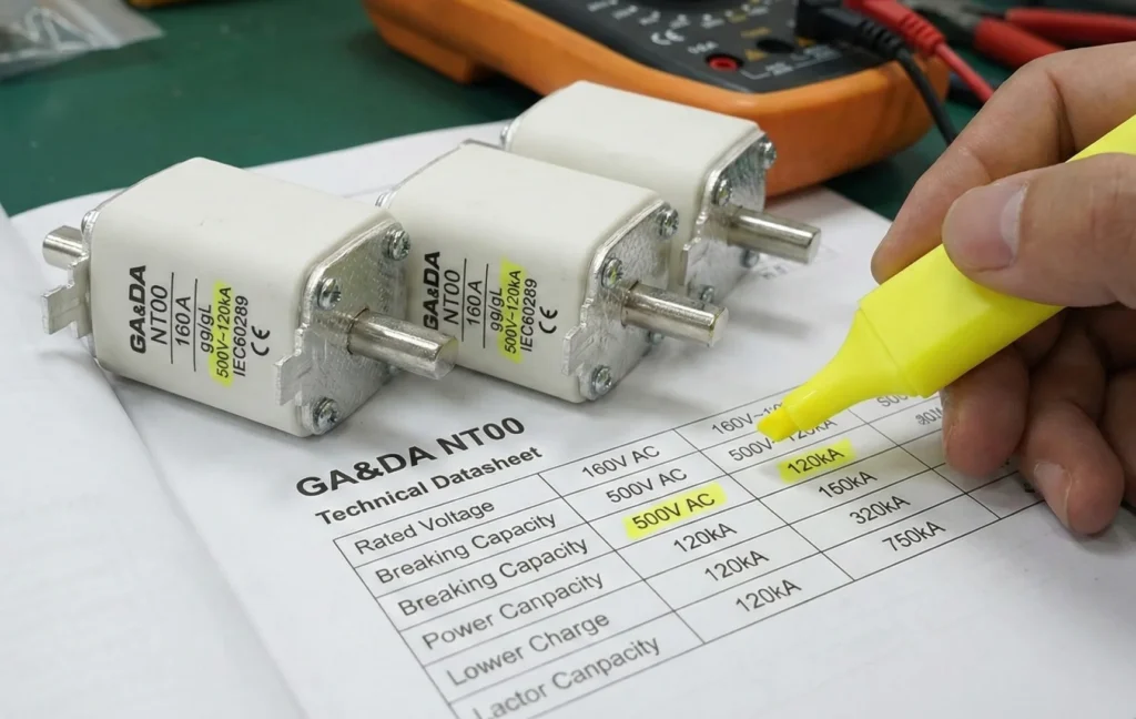
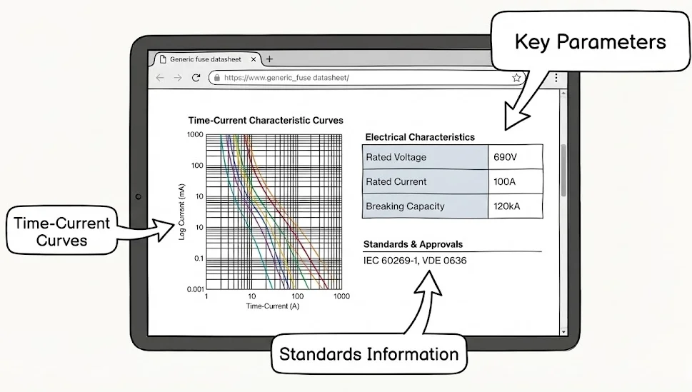
TABLE OF CONTENTS How to read fuse datasheet information correctly is essential if you want to choose protection devices that are truly matched to your system. When you understand how to read fuse datasheet fields such as rated current, voltage, breaking capacity, i²t and time‑current curves, the risk of under‑ or over‑sizing protection drops dramatically. […]
We use cookies to enhance your browsing experience, serve personalised ads or content, and analyse our traffic. By clicking "Accept All", you consent to our use of cookies.