Conception complète d'un système de protection photovoltaïque : SPD, fusible, disjoncteur et boîtier de raccordement
Publié le : Auteur : Rachel
Photovoltaic systems fail in ways that are individually simple and collectively expensive. A DC arc that never clears. A fuse that blows on a cloudy morning. A surge that enters through the PV cable rather than the mains. Each of these sits on the DC side, and each traces back to a protection decision made at design stage.
This guide covers the complete DC protection design for a photovoltaic installation — from array output through the combiner box, string fusing, surge diversion, and main disconnection, to the inverter input. It is written for engineers and technical buyers who need the whole chain specified consistently rather than assembled from parts chosen in isolation.
Table des matières
The DC Protection Chain
A DC side is protected in layers, and each layer handles a different fault type. The layers are not interchangeable, and a gap at one level does not get compensated by a stronger device at another.
The three fault types to design against are: sustained overcurrent (insulation degradation, a shading-induced current imbalance, a fault to earth), transient overvoltage (lightning, switching transients, grid events), and arc faults, which combine both and are the most destructive in PV systems because DC does not self-extinguish at a zero crossing.
Against that background, five layers sit between the array and the inverter. Each one is covered below in the order it appears physically in the circuit.
Layer 1: String Fusing
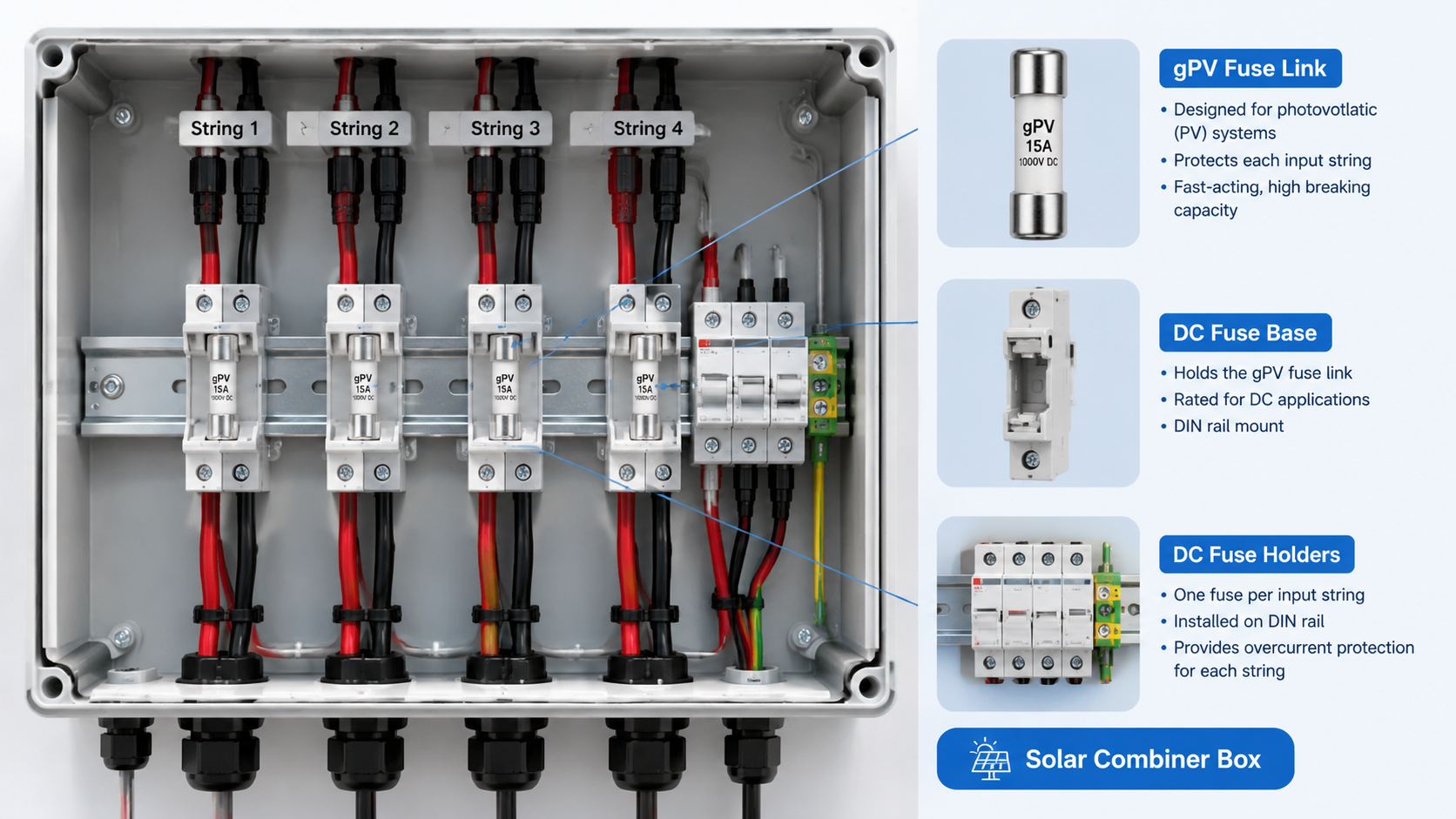
Every PV string gets its own fuse at the point where the string enters the combiner box. Its job is narrow and specific: isolate one faulty string so the remaining strings keep producing. Without it, a single ground fault on one string can take down the entire array.
The sizing rule is well established. Select a fuse rated between 1.25 and 1.5 times the string short-circuit current (Isc), then verify against the time-current curve that it clears within the maximum time the conductor can withstand. The lower bound prevents nuisance blowing from inrush and moderate irradiance transients; the upper bound guarantees the conductor is protected.
PV fuses must be gPV type, rated to IEC 60269-6. This standard exists specifically for photovoltaic strings and addresses a problem general DC fuses do not solve: when a fuse element melts inside a DC string, the surrounding plasma sustains an arc that does not naturally extinguish at a current zero, because DC current has no zero crossing. gPV fuses are tested for that duty — at 1.35 times rated current for PV-specific endurance, and with the rated breaking capacity verified at the actual system voltage.
Using a general-purpose DC fuse rated for the same current is a common and costly substitution. It may pass a bench test at 250 V DC and still fail to interrupt predictably at 1000 V DC.
GA&DA’s fuses and fuse holders range includes gPV fuse links such as the GD-12PV and GD-13PV series, paired with the GDPV series fuse bases for DIN-rail or panel mounting inside the enclosure.
Layer 2: Surge Diversion
A surge protective device clamps transient overvoltage to a level the equipment downstream can withstand. It does not absorb sustained overvoltage, and it does not interrupt fault current — those are the job of the fuse and the breaker behind it. This division of labour is the single most misunderstood point in PV protection.
Two device types apply to the DC side:
SPD de type 2 — the standard choice for PV DC sides. Installed at the point where the PV cables enter the building or at the combiner box, protecting against induced and direct lightning effects. Requires a dedicated DC backup fuse, because the SPD is a sacrificial component that fails short-circuit at end of life.
SPD de type 1 — required when the installation needs protection against direct lightning current (LPZ 0/1 boundary conditions), typically where PV cables run externally for more than a short distance before entering the building.
The parameter that matters on the DC side is Uc, which must equal or exceed the maximum system voltage, combined with Imax, which must cover the available fault current so the backup fuse can be correctly coordinated. A common error is specifying Imax well below the prospective short-circuit current, which makes correct fuse coordination impossible.
GA&DA’s Type 1 and Type 2 PV surge protective devices, including the G2015PV-BC and G2040PV-BC series, are supplied with the DC backup coordination in mind.
Layer 3: Combiner Box Assembly
The combiner box is where layers 1 and 2 physically meet, along with the aggregated main protection. A properly specified unit contains string fuses, a DC SPD with backup protection, a DC MCB or MCCB on the output, and a lockable isolator — in a single enclosure with a defined Uc, current rating, and IP rating.
Configuring both a DC MCB and a DC SPD in the same enclosure is standard practice on commercial systems, and the two have distinct functions rather than overlapping ones. The SPD clamps the transient; the MCB provides overload and short-circuit protection for the downstream cable and inverter input. Specifying an SPD without a coordinated backup protection, or a breaker without surge diversion, leaves a real gap.
The enclosure itself must be matched to the environment. Plastic IP65 enclosures suit most residential and indoor commercial work; 304 or 316L stainless steel is the correct choice for coastal, marine, and industrial sites where corrosion decides the outcome. See GA&DA’s solar combiner box range for the available configurations.
Layer 4: Main Disconnection
The main DC disconnect provides a visible, lockable isolation point for the whole array. It must be DC-rated for the system voltage — a common failure is an AC-rated switch fitted on the DC side, which may not reliably interrupt the arc and gives operators false confidence.
On larger installations this is a DC MCCB rather than a switch disconnector, giving both isolation and overcurrent protection. GA&DA’s DC MCCB series, including the GDDC(M)1 units rated to 1000 V, cover this position.
Layer 5: Inverter Input
The inverter input protection is usually specified by the inverter manufacturer, but the DC side of the cable between the combiner box and the inverter is not. That cable needs its own overcurrent protection for overcurrent events originating between the two devices.
What must be verified at this interface is the maximum DC input voltage of the inverter against the array’s calculated Voc,adjusted. Mismatch here is a leading cause of inverter damage and warranty disputes, and it is a documentation question as much as a technical one.
System Voltage Selection
System voltage determines the ratings of every device in the DC chain, so it is decided before any of them are specified. The choice is between 1000 V and 1500 V DC, and while it is sometimes framed purely as a cost decision, the consequences run through the whole design.
For a given installed capacity, doubling the system voltage halves the current. This reduces conductor cross-section throughout the DC side, reduces the cross-section of busbars and enclosure current paths, and allows smaller fuse ratings for the same power. In a large installation these savings are substantial, because DC cabling is usually the most expensive part of the installation.
The cost is a narrower device range. Not every fuse, SPD, isolator, or breaker is available at 1500 V, and components that are available cost more. Enclosure ratings may also differ — the GA&DA GDS-PV plastic series is rated to 500 V DC, while the GDT-PV metal series carries 1000 V.
Three constraints bound the decision:
Module voltage class. Modern 1500 V modules have higher Voc per module, which allows fewer modules per string for the same array voltage — and gives more margin against the 1500 V limit.
Inverter input limit. A 1500 V array requires a 1500 V inverter. This is normally the decisive constraint, since the inverter is the most expensive single component and is usually selected first.
DC arc behaviour. Higher DC voltage makes arc interruption harder, which is why DC-rated devices at 1500 V are a narrower category and cost more. This is the reason the DC-rated device requirements exist throughout this guide.
Practical consequence: system voltage is not a free variable. It follows from the inverter selection, and every DC device must then be verified against it. This is the most common place where a mixed-voltage system arises — for instance when one inverter is replaced and the array is not reconfigured, leaving some DC devices below the new operating voltage.
The AC Boundary
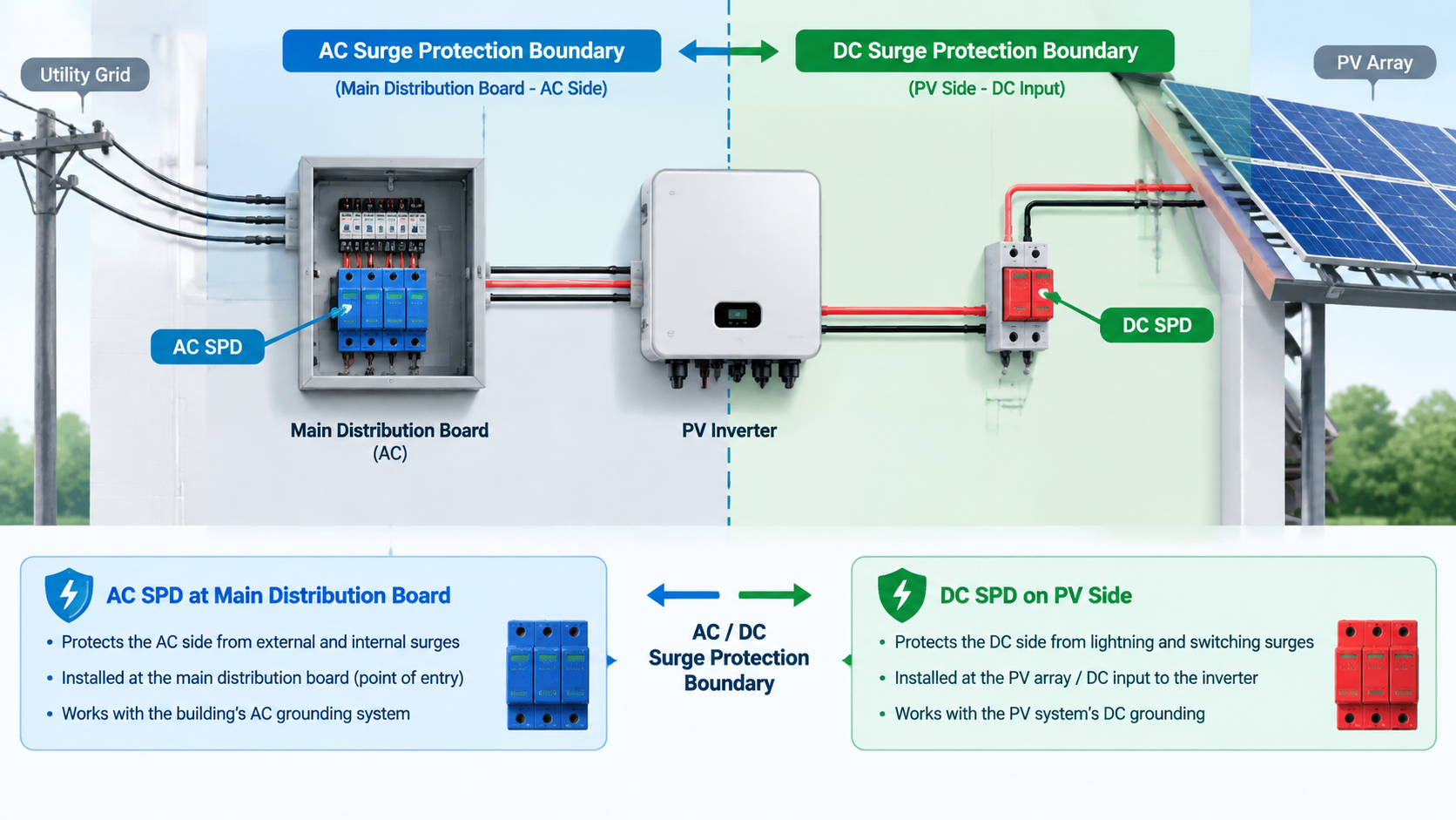
DC and AC surge protection are not interchangeable, and the boundary between them is a design decision with real consequences. An AC SPD relies on the voltage passing through zero twice per cycle, which helps extinguish the arc after the MOVs conduct. A DC SPD cannot rely on that, which is why DC devices are built differently and carry different ratings.
Installation practice is that DC protection is handled at the combiner box and again at the inverter input, while AC protection is handled at the main distribution board and at the final sub-distribution board, per IEC 60364-5-534. Fitting a DC-rated device on the AC side wastes the device; fitting an AC device on the DC side is unsafe.
Coordination Between Devices
Protection only works as a chain if each device’s clearing characteristic is matched to the next. The critical relationships are:
Fuse → SPD backup — the SPD’s Imax must be lower than the breaking capacity of its backup fuse, so the fuse can actually clear the fault when the SPD reaches end of life.
Fuse → conductor — the fuse must clear before the conductor reaches its thermal limit, verified against the time-current curve.
MCB → cable — the breaker’s breaking capacity must exceed the available fault current at its installation point.
SPD → downstream equipment — the SPD’s clamping voltage Up must be below the withstand voltage of everything it protects.
Where these relationships are checked at the design stage, they are routine. Where they are checked after procurement, they generate disputes.
Residual Current Protection
DC arc fault protection has become a significant part of modern PV design, and its interaction with the rest of the protection chain is worth setting out separately.
The reason it matters is specific to DC. In an AC system, an arc fault that develops into a line-to-earth fault is likely to draw enough current to operate an overcurrent device or a fuse. On a DC side, the current required to sustain an arc can remain below the overcurrent threshold — the arc keeps conducting without drawing enough current to trip anything, and continues to damage conductors until it becomes a fire.
DC residual current devices address this by detecting the difference between outgoing and returning current on the DC conductors, which responds to current taking an unintended path rather than returning through the intended circuit. Where installed, they are positioned on the DC side, typically at the inverter or at the point where the DC circuits are combined, and their operating threshold is chosen to detect the leakage current of a developing arc rather than nuisance conditions.
Three points of coordination matter. First, the DC RCD’s own response time and sensitivity must be verified against the inverter’s behaviour on loss of DC input — the inverter must shut down cleanly rather than continuing to attempt to draw current. Second, the DC RCD does not replace fusing; it complements layers 1 through 5 by detecting a fault type they cannot. Third, it must be a device rated for the DC system voltage and for the system’s current, which again is a narrower category than the AC equivalent.
Local electrical codes determine whether DC arc fault protection is mandatory, recommended, or optional, and this varies by jurisdiction. Where it is not code-mandated, it is still relevant on larger installations, where the cost of an undetected DC arc outweighs the device cost.
Common Design Errors
AC-rated devices on the DC side — a DC disconnect or breaker rated only for AC may fail to interrupt a DC arc.
General DC fuses instead of gPV — IEC 60269-6 endurance requirements are specific to PV duty.
SPD without DC backup protection — a failed SPD becomes a permanent short circuit.
Fusing at 1.5 × Isc without checking the time-current curve — compliant on paper, unreliable in service.
Ignoring cold-temperature voltage rise — sizing Voc,adjusted at STC rather than at minimum temperature underestimates array voltage and can exceed component ratings.
No isolation point — array cannot be safely serviced.
Mixing brands across the chain — coordination curves cannot be verified when devices were selected independently.
A Practical Specification Checklist
For any PV DC protection design, the following should be confirmed before purchase:
Voc,adjusted calculated at minimum module temperature, not at STC
String fuse rating between 1.25 and 1.5 × Isc, verified against the time-current curve
Fuses certified gPV to IEC 60269-6
SPD type (1 or 2) justified by the installation’s lightning protection zone
SPD Uc ≥ system voltage; Imax coordinated with the DC backup fuse
DC-rated main disconnect, lockable, rated for the system voltage
MCB/MCCB breaking capacity ≥ available fault current
DC arc fault protection included where code-mandated or justified by installation size
Enclosure material and IP rating matched to the environment
All components rated for the actual system voltage, not a nominal figure
Inverter maximum DC input voltage confirmed above the array’s adjusted Voc
MPPT input count on the inverter matched to the box configuration and string layout
GA&DA supplies the full DC protection chain for photovoltaic systems — solar combiner boxes in plastic and 304/316 stainless steel enclosures, Type 1 and Type 2 surge protective devices including PV-specific models, gPV fuse links and holders, and DC miniature and moulded case circuit breakers. Components can be specified as one coordinated assembly, or supplied individually against your own panel specification.
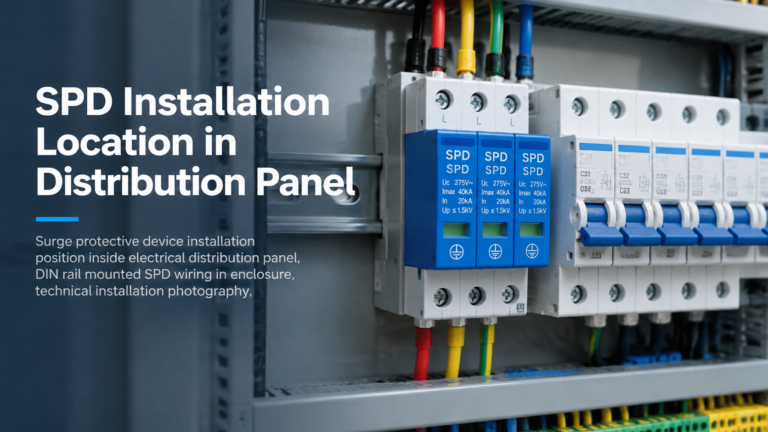
Where a surge protective device is installed determines how much of the surge it actually intercepts. A correctly specified device placed in the wrong position provides far less protection than its datasheet suggests — and because the installation still looks compliant, the shortfall is rarely detected until equipment fails. This guide covers surge protective device […]
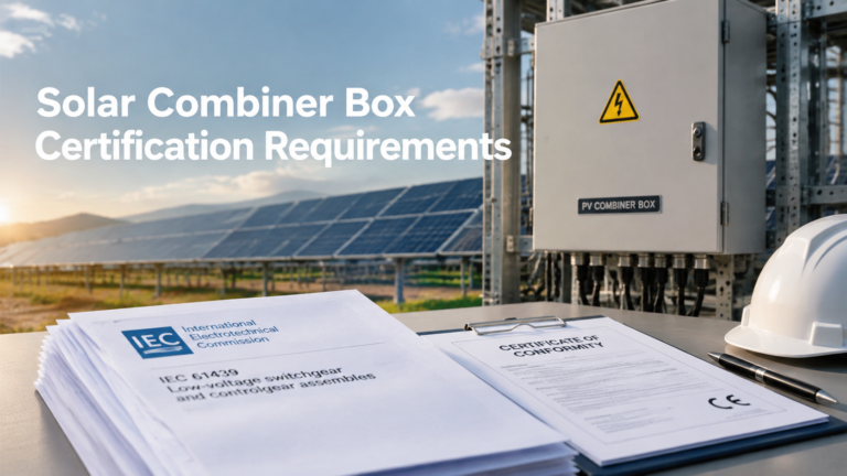
Certification requirements sit between a solar combiner box being technically suitable and being accepted. In practice, a box that meets every functional requirement can still be rejected at tender stage or on site because the documentation supporting its conformity does not match what the market expects. This is a documentation and compliance topic rather than […]
Most solar combiner box datasheets open with a table of ratings, and most buyers skim past it. That table is where the decision actually gets made. A combiner box is a passive enclosure — it does not protect anything by itself — so every number on its datasheet is either a limit you must stay […]