Solar Combiner Box Specifications: How to Read Datasheets Before You Buy
Publié le : Auteur : Rachel
Most solar combiner box datasheets open with a table of ratings, and most buyers skim past it. That table is where the decision actually gets made. A combiner box is a passive enclosure — it does not protect anything by itself — so every number on its datasheet is either a limit you must stay inside or a claim you need to verify before you rely on it.
This guide walks through the parameters that matter when you specify a photovoltaic combiner box: what each rating means, which ones are non-negotiable, and where the datasheet is usually optimistic. It is written for procurement and engineering teams who need to compare boxes from different suppliers on equal terms rather than on the highest number printed.
Table des matières
1. String Configuration and Circuit Count
The first thing to read on a combiner box datasheet is not a rating at all — it is the configuration. A box described as 1/6 means one input string feeding six outputs, which is not the same device as a 6/1 box with six inputs feeding one output. Suppliers frequently list both under similar names.
Configuration determines current handling, not voltage. Each input string carries its full string current, so a 1/16 box is a distribution panel for a single array, while a 16/1 box is a collector for sixteen parallel circuits. The enclosure size, busbar cross-section, and fuse count all follow from this decision.
For residential and small commercial work, 1/2 through 1/6 covers most cases. Utility-scale plants use multiple 12/16 or 16/1 units in parallel rather than one very large box, because splitting into several enclosures keeps each string circuit short and serviceable.
2. Voltage Rating (Uc) and Where It Comes From
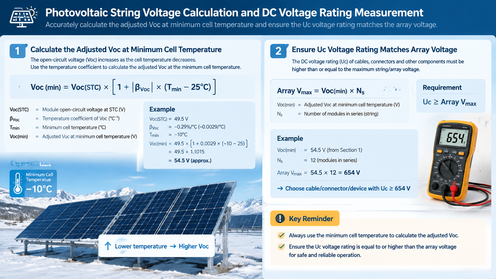
Uc is the maximum system voltage the box is rated to handle. On photovoltaic systems it must exceed the maximum DC voltage of the connected string, which is calculated as:
Voc,adjusted = Voc,STC x (1 + temperature coefficient x (Tmin,cell - 25))
Two things make this calculation unforgiving. First, the temperature coefficient is negative for virtually all crystalline silicon modules, so the string voltage rises at the coldest point — a cold winter morning, not a hot summer noon. Second, on a cold morning the string may not reach its open-circuit voltage instantly, so the calculation window can last minutes, not seconds.
In practice this is why 1000 V and 1500 V systems exist. A 1500 V array halves the current for the same power, which reduces cable cross-section and combiner box busbar thickness. If your datasheet lists a 1000 V Uc, confirm it is rated for the array’s calculated Voc,adjusted, not merely for the nominal system voltage.
GA&DA’s plastic boxes are rated to 500 V DC, while the stainless steel GDT-PV series carry a 1000 V DC rating. The choice is not about quality — it is about matching the array voltage.
3. Current Rating: Isc versus Ifm
Two different current figures appear on PV equipment, and confusing them is a common procurement error.
Isc (short-circuit current) is the maximum current a string can produce. Fuse holders, busbars, and switchgear inside the combiner box must be rated well above Isc.
Ifm (maximum current drawn) reflects array output under operating conditions — typically 80–90% of Isc.
For DC fuse sizing, the practice is to select a fuse rated between 1.25 and 1.5 times the string Isc, then confirm the fuse’s time-current curve still clears the array’s available fault current within the required time. A fuse rated above 1.5 times Isc may fail to protect the conductor; one rated below 1.25 times may nuisance-blow on inrush.
When you compare supplier datasheets, check whether the stated current rating is Isc-based or Ifm-based. A box claiming “80 A” without qualification may mean 80 A continuous output at a lower Isc, which is not directly comparable to a competitor’s 80 A Ifm rating.
4. Protection Devices Inside the Box
A combiner box that ships without protection devices is an enclosure, not a combiner. Four components normally determine the configuration, and the datasheet should specify each one by type and rating rather than leaving them as options.
DC fuses — one per input string, sized to 1.25–1.5 × Isc. For PV applications these must be gPV-rated to IEC 60269-6, not generic DC fuses.
DC SPD — Type 2, with a dedicated DC backup fuse or disconnection device. The SPD’s Uc must match or exceed the system voltage.
DC MCB or MCCB — the main disconnect, providing overcurrent protection on the aggregated output.
DC isolator / switch disconnector — for safe maintenance isolation, lockable in the open position.
The combination of DC MCB and DC SPD inside one enclosure is standard for commercial systems: the SPD clamps surge events, the MCB provides the overcurrent backup that clears a failed or sustained overvoltage. Specifying only one of the two leaves a gap.
GA&DA supplies the matching components for these positions — Type 1/2 PV SPDs, gPV fuse links such as the GD-12PV and GD-13PV series, and DC fuse bases including the GDPV-22B and GDPV-50 — so the box can be specified as a complete assembly rather than a shell to be fitted out separately.
5. Enclosure Material and IP Rating
IP65 and IP66 are both common on PV combiner boxes, and the difference is not marginal. IP65 protects against water jets from any direction; IP66 adds protection against powerful water jets used in fire-hose testing. Neither rating includes IP67, which requires immersion protection.
Material follows from installation environment rather than from a preference:
PVC / ABS plastic enclosures — cost-effective, corrosion-resistant, and electrically insulating. Suitable for most residential and indoor commercial installations. UV stabilisation matters for outdoor exposure.
Stainless steel (304 / 316L) — for marine, coastal, industrial, and desert installations where corrosion resistance or mechanical robustness decides the outcome. 316L is the standard choice within a few kilometres of saltwater.
One practical note on metal enclosures: bonding and earthing become part of the installation, and the datasheet should show the earthing stud position and the cross-sectional area it accepts. Plastic enclosures need no bonding but require the metallic parts inside them to be bonded for fault current paths.
GA&DA’s GDS-PV series uses plastic enclosures rated IP65, and the GDT-PV8 and GDT-PV16 use 304/316 stainless steel for higher-corrosion environments.
6. Standards and Certification
PV combiner boxes are covered by IEC 61439-1 (general rules) and IEC 61439-2-2 (PV utility-scale assemblies), with the low-voltage switchgear part of IEC 61439-3 covering the internal switching devices. For the European market, TUV and VDE marks are frequently required beyond the IEC declaration. In North America, UL 50E covers the enclosure and UL 1449 covers the surge protective devices themselves.
The distinction worth drawing is between a declaration of conformity and a third-party certification. A declaration states the manufacturer asserts the product meets the standard. Third-party marks involve an external body that has examined or tested the product. For tender documentation in Europe, the second is usually required.
7. Temperature Derating and Altitude
Rated current in a datasheet is measured at a reference temperature, typically 25 °C. Installed combiner boxes on a rooftop or in an unheated enclosure routinely operate at 50–70 °C. Because busbars and terminals lose roughly 0.4–0.5% of rated current per °C above the reference point, a device rated 100 A at 25 °C may carry around 85 A at 50 °C.
Altitude also matters: air’s insulating strength drops with pressure, so above roughly 2,000 m the clearance distances specified in the standard no longer hold without correction. Datasheets for equipment intended for high-altitude sites should state a derating curve or a maximum altitude.
Ask specifically how the rated current was measured — per string or in aggregate, and at what ambient temperature. This single clarification prevents most sizing disputes between suppliers.
8. Matching the Box to the Inverter
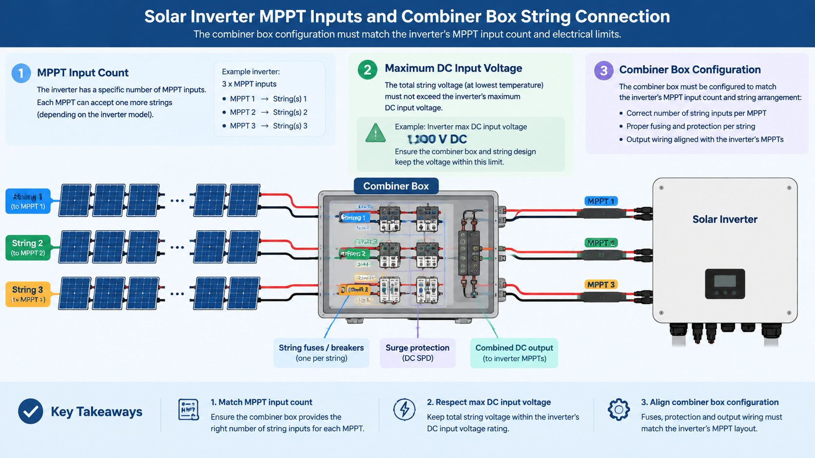
The combiner box is not an independent component. Its outputs define what the inverter can be connected to, and three parameters determine whether the two match.
Maximum DC input voltage. The inverter datasheet states a maximum DC input voltage, commonly 1000 V or 1500 V. The array’s calculated Voc,adjusted must stay below this figure with margin. This is not a nominal comparison — the margin matters, because Voc,adjusted reflects the coldest conditions at the site, and the value used in design may differ from the value realised if the array is reconfigured or modules substituted.
MPPT input count and current. Most inverters have a fixed number of MPPT inputs, each with a maximum input current. A 1/4 box feeding a four-string inverter works only if that inverter has four MPPT inputs accepting the aggregate current. If it has two MPPT inputs, the four strings must be combined into two inputs — and that parallel combination requires separate fusing at the point of paralleling, which is exactly what a 1/4 box provides if configured correctly. A 4/1 box feeding two MPPT inputs does not.
This mismatch is one of the most common design errors in PV work, and it is entirely avoidable at the specification stage: count the MPPT inputs, decide how many strings are being paralleled, and select the box configuration to match. It also determines whether string-level monitoring is possible at all — a box that combines strings before they reach their own MPPT inputs loses per-string data.
Input voltage range per MPPT. Beyond the maximum, inverters also specify a minimum start-up and operating voltage per MPPT input. Arrays designed for high temperature may fall below this at low irradiance if strings are too short, producing a system that works in winter and stalls in summer. The same Voc,adjusted calculation runs in reverse, using the highest expected cell temperature to confirm the string voltage stays inside the operating window.
9. Earthing and Conductor Sizing
Two sets of conductors connect to a combiner box: the PV DC conductors carrying string current, and the protective earth conductors bonding the enclosure and its internals. They have different purposes and different sizing rules, and conflating them is a common documentation error.
DC conductors. Sized on the string current, not on the aggregate box rating. The sizing basis is typically the ampacity at the highest ambient temperature expected, with the applicable derating factors applied for temperature, grouping, and where relevant, altitude. Cable insulation must be rated for the system voltage and suitable for DC, with the temperature rating matching the worst-case condition rather than the average. Using AC-rated insulation on the DC side is a recurring specification error; the voltage rating alone is not the same thing as DC suitability.
Protective earth conductors. These bond the enclosure, the DIN rail, the fuse bases, and any metallic internal components. Where the enclosure is metallic, this is the primary safety provision. The earthing stud position and the cross-sectional area it accepts should appear on the datasheet, and the assembly must be verified for the prospective fault current it could carry.
In plastic enclosures, internal metallic parts still require bonding — the SPD earth terminal, the DIN rail, and the fuse bases. The difference is that the enclosure itself does not contribute, so the internal bonding arrangement carries more of the fault current responsibility.
Cable entries and gland types. The number, size, and orientation of entries is often determined by the incoming and outgoing conductor sizes, which are themselves determined by the string count and current. This makes gland layout a consequence of the electrical design rather than a mechanical afterthought, and it is why combiner boxes are commonly supplied with entries and glands pre-configured to the order. Specifying the entry sizes with the order avoids field modification of an enclosure already certified as an assembly.
10. Questions to Ask Before You Order
Is the stated voltage rating Uc, and is it continuous DC or AC?
Is the current rating based on Isc or Ifm, and at what ambient temperature?
Which protection devices are included as standard, and which are optional?
Are the fuses gPV-rated to IEC 60269-6, and does the SPD include a DC backup fuse?
What is the enclosure material, IP rating, and UV stabilisation level?
Which standards does the box declare, and which third-party marks are available?
What is the maximum altitude the ratings are valid for?
Can dimensions and cable entry sizes be adapted for a particular layout?
That last question matters more than it appears. A combiner box mounted in a tight equipment room may need rotated cable entries or a different gland plate layout. That kind of adaptation is routine for manufacturers who build to order, and impossible to retrofit later.
Related GA&DA Products
Solar combiner boxes from GA&DA are available in plastic IP65 and 304/316 stainless steel enclosures, with gPV fuses, Type 1/2 PV surge protective devices, DC fuse bases, and DC disconnectors supplied to match the enclosure. See the full solar combiner box range, or browse dispositifs de protection contre les surtensions et fuses and fuse holders for the components specified inside these enclosures.
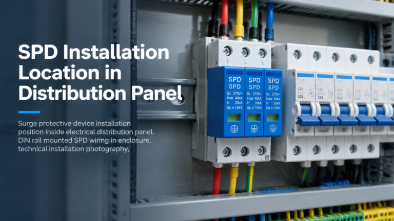
Where a surge protective device is installed determines how much of the surge it actually intercepts. A correctly specified device placed in the wrong position provides far less protection than its datasheet suggests — and because the installation still looks compliant, the shortfall is rarely detected until equipment fails. This guide covers surge protective device […]
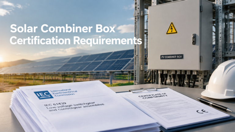
Certification requirements sit between a solar combiner box being technically suitable and being accepted. In practice, a box that meets every functional requirement can still be rejected at tender stage or on site because the documentation supporting its conformity does not match what the market expects. This is a documentation and compliance topic rather than […]
Les défaillances des installations photovoltaïques sont, prises individuellement, simples, mais, cumulées, elles s’avèrent coûteuses. Un arc électrique en courant continu qui ne s’éteint jamais. Un fusible qui saute par un matin nuageux. Une surtension qui pénètre par le câble photovoltaïque plutôt que par le réseau électrique. Chacun de ces problèmes se situe du côté du courant continu, et chacun trouve son origine dans un choix de protection effectué […]