Selecting the right fuse rating for electrical circuits is one of the most critical decisions in electrical system design and installation. The fuse rating determines how much current can flow safely through a circuit before the fuse operates to protect against overcurrent conditions. Choosing the correct fuse rating ensures reliable circuit protection without nuisance operations, prevents equipment damage, and maintains electrical safety for personnel and property. Many electrical fires and equipment failures result directly from improperly rated fuses—either oversized fuses that fail to protect or undersized fuses that operate unnecessarily during normal conditions.
The process of fuse rating selection involves analyzing circuit load characteristics, calculating maximum operating current, accounting for ambient conditions, and coordinating protection with conductors and other devices. Whether installing AC fuse bases in residential distribution panels, DC fuse systems in solar photovoltaic installations, or industrial fuse links in heavy equipment, proper fuse rating selection requires understanding load behavior, electrical codes, and manufacturer specifications. This comprehensive guide provides engineers, electricians, and facility managers with practical methods for selecting appropriate fuse ratings across various applications, ensuring both adequate protection and reliable operation.
Understanding Fuse Rating Basics
What is Fuse Rating?
Fuse rating refers to the nominal current value that a fuse can carry continuously at a specified ambient temperature—typically 25°C or 40°C depending on the applicable standard—without operating or experiencing excessive temperature rise. This rating represents the maximum steady-state current for which the fuse is designed, expressed in amperes. For example, a 10A rated fuse should safely carry 10 amperes indefinitely under reference conditions without melting its internal element or degrading its protective characteristics. The fuse rating fundamentally defines the fuse’s current-carrying capacity under normal operating conditions.
However, understanding fuse ratings requires recognizing that fuses don’t operate at exactly their rated current. Fuse standards specify tolerance bands around the rated value. A fuse must not operate at its rated current (100%) but must operate within a specified time at the conventional fusing current, typically 135% of rating for general purpose fuses. This means a 10A fuse will not blow at 10A but will definitely operate within one to four hours at 13.5A, depending on the specific standard and fuse type. This characteristic provides necessary margin for normal load variations while ensuring reliable protection during sustained overload conditions.
The relationship between fuse rating and actual operating current follows complex time-current characteristic curves provided by manufacturers. At 110% of rated current, a fuse might take many hours to operate. At 135-150%, operation occurs within minutes to an hour. At 200% of rating, operation might take only seconds, while short-circuit currents thousands of times the rating trigger near-instantaneous response. Engineers must carefully match fuse ratings to circuit requirements by considering these time-current relationships alongside load characteristics and protection objectives.
Current Rating vs Load Current
A fundamental principle in fuse rating selection distinguishes between the fuse’s current rating and the circuit’s maximum load current. The fuse rating must exceed the normal operating current to prevent nuisance operations during routine conditions, yet remain low enough to provide adequate protection against overloads and coordinate properly with conductor ampacity. Industry best practice recommends sizing fuse ratings at 125% to 150% of the maximum continuous load current for most applications. This sizing provides sufficient margin for normal load fluctuations, voltage variations, and momentary surges while ensuring the fuse operates reliably during sustained overload or fault conditions.
For example, if a circuit supplies a continuous load of 16 amperes, simply installing a 16A fuse would be inappropriate. Normal voltage variations, ambient temperature changes, and load cycling could cause the fuse to operate unnecessarily. Instead, selecting a 20A or 25A fuse provides adequate operating margin while still protecting against dangerous overloads. However, this selection must also verify that the circuit conductors have adequate ampacity—the 20A fuse protecting 16A load should be installed in conductors rated for at least 20A continuous current to ensure proper coordination.
The distinction between fuse rating and load current becomes particularly important in applications with varying loads or duty cycles. Intermittent loads that cycle on and off may have peak currents significantly exceeding average current. Continuous loads operating 24/7 require more conservative fuse rating selection than intermittent loads operating a few hours daily. Equipment nameplates typically specify full-load current, but actual operating current may differ based on conditions. Measuring actual circuit current under various operating scenarios provides the most reliable data for fuse rating selection, preventing both undersizing and oversizing issues.
The 125% Rule for Fuse Rating
The “125% rule” represents a widely accepted guideline in electrical codes and engineering practice for fuse rating selection in continuous-duty applications. This rule states that the fuse rating should be at least 125% of the continuous load current. The National Electrical Code (NEC) and similar international standards incorporate this principle to ensure overcurrent protection devices don’t operate under normal continuous loading while still providing adequate protection. For instance, a circuit with 40A continuous load should use a minimum 50A fuse (40A × 1.25 = 50A) to comply with this requirement.
The 125% rule recognizes several practical realities in electrical system operation. First, fuses experience temperature rise when carrying current, which reduces their current-carrying capacity. Operating a fuse at exactly its rated current in an elevated ambient temperature might cause premature operation. Second, the rule accounts for normal load variations—equipment doesn’t draw perfectly constant current, and minor fluctuations shouldn’t trigger protective devices. Third, it provides coordination margin ensuring fuses operate only during genuine overload or fault conditions, not during normal operation including reasonable transients.
However, the 125% rule represents a minimum guideline, not an absolute requirement for all situations. Some applications may require more conservative sizing at 150% or even 200% of load current, particularly for loads with high starting currents like motors, transformers, or equipment with significant inrush characteristics. Conversely, critical circuits protecting sensitive equipment might use fuse ratings closer to 110-115% of load current for enhanced protection, though this increases risk of nuisance operations. Engineers must balance the competing objectives of reliable protection versus operational continuity when applying the 125% rule to specific circumstances.
Key Factors in Selecting Fuse Rating
Normal Operating Current Calculation
Accurate determination of normal operating current forms the foundation for proper fuse rating selection. For resistive loads such as heating elements or incandescent lighting, calculating operating current involves straightforward application of Ohm’s law: current equals power divided by voltage (I = P/V). A 2400-watt heater on a 240V circuit draws 10 amperes continuously (2400W ÷ 240V = 10A). For such applications, selecting a fuse rating at 125-150% of calculated current—12.5A to 15A in this example—provides adequate protection. Most practical installations would use a 15A fuse for this 10A continuous load.
For three-phase equipment, current calculations become slightly more complex. Three-phase power formula (P = √3 × V × I × PF) requires knowing voltage, power factor (PF), and total power to calculate line current. A 10 kW three-phase motor operating at 400V with 0.85 power factor draws approximately 16.9 amperes per phase. Calculating line current correctly ensures proper fuse rating selection for each phase conductor. Unbalanced three-phase loads require analyzing each phase separately, selecting fuse ratings based on the highest-loaded phase while maintaining balance across all three phases.
Multiple loads on a single circuit require adding individual load currents, though not all loads necessarily operate simultaneously. Applying demand factors and diversity factors according to electrical codes allows realistic assessment of maximum expected current rather than simple arithmetic summation. For instance, residential circuits supplying multiple outlets don’t see all outlets loaded to maximum simultaneously. Commercial HVAC systems may have staggered start sequences preventing all compressors from running together. Understanding actual load profiles through measurement or detailed analysis enables optimized fuse rating selection that provides protection without excessive over-sizing.
Starting and Inrush Currents
Inductive loads including motors, transformers, solenoids, and contactors draw significantly higher current during starting or energization compared to steady-state running current. Motor starting current typically ranges from 6 to 10 times full-load current depending on motor type, with locked-rotor conditions potentially exceeding these values. A 10-horsepower motor with 14A full-load current might draw 84A to 140A during starting for several seconds. Transformer inrush current can reach 8-12 times rated current during initial energization, lasting one to two seconds as the magnetic core saturates and stabilizes.
Fuse rating selection for circuits supplying inductive loads must accommodate these starting transients without nuisance operation while still protecting against sustained overloads and short circuits. Time-delay fuses specifically designed for motor applications tolerate high starting currents for several seconds yet still provide reliable overcurrent protection. Selecting time-delay fuse systems rated at 175-250% of motor full-load current typically provides proper coordination. For example, the 10 HP motor with 14A full-load current might use a 30A or 35A time-delay fuse that withstands brief starting currents but protects against locked-rotor conditions.
Capacitive loads present the opposite challenge—high inrush current during energization that quickly decays. Power factor correction capacitor banks can draw 10-20 times rated current for several milliseconds when switched on, as the capacitor charges to system voltage. Semiconductor equipment with input filter capacitors exhibits similar behavior. While these inrush events are very brief, they can cause fast-acting fuses to operate unnecessarily. Fuse rating selection for capacitive loads typically uses ratings 150-200% of steady-state current, sometimes paired with current-limiting devices or soft-start circuits to reduce inrush magnitude. Understanding load characteristics proves essential for matching fuse types and ratings to application requirements.
Ambient Temperature Effects
Ambient temperature significantly affects fuse performance and current-carrying capacity, making temperature considerations essential in fuse rating selection. Fuses are rated at reference ambient temperatures—typically 25°C for most standards. When installed in higher ambient temperatures, fuses carry less current before operating because external heat adds to internally generated I²R heating. For every 10°C rise above reference temperature, typical fuses require derating by approximately 5-10% depending on construction. A 10A fuse rated at 25°C might require derating to 9A or 9.5A capacity when installed in a 45°C enclosure.
Manufacturer datasheets provide specific temperature derating curves showing the relationship between ambient temperature and allowable continuous current. These curves vary significantly between fuse types—some designs tolerate higher temperatures better than others. Engineers must identify the actual ambient temperature at the fuse installation location, not the general room temperature. Inside closed electrical panels, enclosures, or near heat-generating equipment, ambient temperatures can exceed room temperature by 20-30°C or more. Measuring actual enclosure temperatures or using thermal analysis ensures accurate temperature derating.
Conversely, extremely cold ambient temperatures increase fuse current-carrying capacity but may affect response characteristics. Solar photovoltaic systems operating in winter conditions experience both elevated voltages due to temperature effects on PV cells and potentially lower ambient temperatures affecting DC fuses. Some fuse types become more sensitive to transients at very low temperatures. Design specifications should account for the full operating temperature range—from coldest winter conditions to hottest summer temperatures—selecting fuse ratings that provide adequate protection and reliability across the entire envelope. When temperature derating is significant, selecting the next higher standard fuse rating often proves necessary.
Fuse Rating Selection for Different Load Types
Resistive Loads: Heating and Lighting Circuits
Resistive loads represent the simplest case for fuse rating selection because they draw relatively constant current without significant starting transients or power factor considerations. Electric resistance heating elements, incandescent lighting, and similar loads behave predictably—current equals voltage divided by resistance, remaining stable during operation. For these applications, fuse rating selection follows straightforward calculation: determine total connected load in watts, divide by system voltage to find amperes, then select a fuse rated at 125-150% of this value. A 15A fuse appropriately protects a 2880-watt heating circuit on a 240V system (2880W ÷ 240V = 12A; 12A × 1.25 = 15A minimum).
However, some considerations apply even to resistive loads. Cold filaments in incandescent lamps draw briefly higher current during the first milliseconds of energization before heating to operating temperature—typically 10-15 times steady-state for just a few milliseconds. While this rarely causes problems, simultaneous energization of many incandescent lamps might occasionally trigger fast-acting fuses. LED lighting eliminates this concern but introduces power supply inrush currents instead. Electric heaters with thermostatic controls cycle on and off, and the fuse must tolerate repeated cold-start transients without degradation over years of service.
Resistive load circuits also require verifying conductor ampacity matches or exceeds fuse rating. A 15A fuse protecting 12A load requires at least 15A-rated conductors, which according to most electrical codes means minimum 14 AWG copper wire. The fuse protects both the load equipment and the supply conductors. Using undersized conductors with properly rated fuses defeats the protection system—the conductors might overheat before the fuse operates. Proper fuse rating selection for resistive loads achieves the balance between adequate circuit protection, reliable operation, and coordination with all system components including conductors, switches, and terminals.
Inductive Loads: Motors and Transformers
Inductive loads present the most complex challenges for fuse rating selection due to their high starting currents, reactive power characteristics, and diverse operating modes. Three-phase motors, single-phase motors, transformers, solenoids, and electromagnetic equipment all exhibit inductive behavior. Motor fuse rating selection typically ranges from 150% to 250% of motor full-load current depending on starting method, duty cycle, and desired protection level. Direct-on-line (DOL) motor starting with high inrush requires larger fuse ratings than soft-start or variable frequency drive (VFD) starting with limited current.
The type of fuse matters critically for motor applications. Fast-acting fuses would operate unnecessarily during motor starting, while time-delay fuses specifically engineered for motor protection tolerate starting transients while still protecting against locked-rotor and overload conditions. Motor-rated fuses feature dual-element construction or special element designs that distinguish between brief harmless starting currents and sustained dangerous fault currents. For a 50 HP three-phase motor with 65A full-load current, appropriate protection might use 100A to 150A time-delay motor fuses depending on starting characteristics and coordination requirements with upstream and downstream devices.
Transformer primary fuse rating selection follows similar principles, typically sized at 150-300% of primary full-load current. Transformers draw high magnetizing inrush current during energization that decays over one to two seconds. Small transformers (under 1 kVA) might use fuse ratings at 125-150% of primary current, while large power transformers require 200-300% to accommodate inrush without nuisance operation. Secondary circuit protection requires separate analysis based on secondary load characteristics. Circuit breakers and fuses should coordinate so the most downstream device nearest the fault operates first, clearing problems with minimal system disruption.
Capacitive Loads: Power Factor Correction
Capacitive loads including power factor correction banks, filter capacitors, and DC link capacitors in variable frequency drives present unique fuse rating selection challenges. When first energized, an uncharged capacitor appears as a short circuit, drawing very high inrush current limited only by system impedance. This inrush current can reach 10-30 times steady-state current for several milliseconds until the capacitor charges to system voltage. While brief, this inrush can damage contactors, cause voltage dips affecting other equipment, and potentially operate fast-acting fuses unnecessarily.
Fuse rating selection for capacitor circuits typically uses ratings 135-150% of capacitor rated current, with careful consideration of fuse type and speed. Some engineers specify time-delay fuses to accommodate inrush, though standard time-delay periods may be too long for optimal capacitor protection. Specialized fuses for capacitor applications offer compromise characteristics—fast enough to protect against capacitor failures but tolerant of energization inrush. Additionally, many modern installations include inrush limiting resistors or reactors that reduce peak inrush current, allowing use of smaller, faster fuses that provide better protection.
Power factor correction systems with multiple capacitor steps switching on and off present additional complexity. Each switching event generates inrush current, and if steps switch rapidly, accumulated thermal stress on fuses can cause premature failure or characteristic drift. Automatic power factor controllers must be programmed with appropriate time delays between switching events, typically 30-60 seconds minimum, allowing fuses to cool between inrush events. Proper fuse rating selection for these systems requires analyzing worst-case switching scenarios, accounting for both steady-state reactive current and repetitive inrush transients. Coordination with capacitor contactors and protection relays ensures the entire protection system operates reliably over years of service.
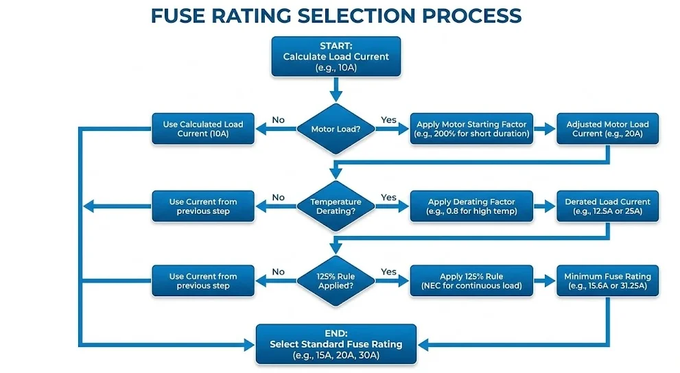
Step-by-Step Fuse Rating Selection Process
Calculate Maximum Continuous Current
The first step in proper fuse rating selection involves accurately determining the maximum continuous current the circuit will carry during normal operation. For simple resistive loads, this calculation follows directly from power and voltage: I = P/V. Sum all connected loads, apply appropriate demand factors if not all loads operate simultaneously, and calculate total current. For example, a 240V circuit supplying 4800 watts of continuous heating load draws 20 amperes (4800W ÷ 240V = 20A). This represents the baseline current value for subsequent fuse rating selection steps.
For more complex loads, measurement provides the most reliable data. Using a true RMS ammeter, measure actual circuit current under maximum load conditions including all equipment energized and operating at full capacity. Take measurements over sufficient time to capture load variations—motor cycling, heating elements switching, lighting changes, and other dynamic behavior. Record peak continuous current (not instantaneous peaks during starting) as the basis for fuse rating selection. If measurement isn’t feasible, use equipment nameplate data conservatively, adding safety margins for unknown factors and future load growth.
Three-phase circuits require measuring all three phases and using the highest value for fuse rating selection. Unbalanced loads may show significantly different currents on each phase. Single-phase loads distributed across three-phase systems need careful analysis to ensure each phase has appropriate protection. Document all calculations and measurements for future reference and code compliance verification. This documentation should include connected loads, calculation methodology, measured values if available, applicable codes and standards, and justification for selected fuse ratings. Proper documentation facilitates inspections, future modifications, and troubleshooting.
Apply Safety Factors and Derating
After determining maximum continuous current, apply appropriate safety factors and derating multipliers to account for operating conditions, code requirements, and reliability margins. The fundamental 125% rule provides the minimum starting point—multiply maximum continuous current by 1.25 for the baseline fuse rating. For the previous example of 20A continuous current, minimum fuse rating becomes 25A (20A × 1.25 = 25A). However, additional factors may require further upward adjustment from this baseline.
Temperature derating represents the most common additional factor. If the fuse installation location experiences elevated ambient temperature—common inside enclosed panels or near heat sources—apply temperature derating factors from manufacturer data. A fuse in a 50°C environment might require 10-15% derating, increasing the effective fuse rating need. For our example, if 10% temperature derating applies, the required fuse rating increases to approximately 28A (25A ÷ 0.9 = 27.8A). Since fuses come in standard ratings, select the next higher standard size—30A in typical fuse rating series.
Other derating factors include altitude (for high-elevation installations), duty cycle (for repetitive high-current pulses), and aging (for critical long-term reliability). Some engineers apply an additional 10-15% growth margin for future load additions, preventing need for replacement when minor load increases occur. After applying all relevant factors, select the next available standard fuse rating that meets or exceeds the calculated requirement. Standard fuse ratings typically follow E6 or E12 series: 6A, 10A, 16A, 20A, 25A, 32A, 40A, 50A, 63A, 80A, 100A, etc. Always round up to the next standard rating—never interpolate or assume non-standard ratings are acceptable.
Verify Cable Ampacity and Coordination
The final critical step in fuse rating selection verifies that selected fuse ratings properly coordinate with conductor ampacity and other protective devices. The fundamental principle: conductor ampacity must equal or exceed fuse rating to ensure the fuse protects the conductor against damage from overcurrent. If you select a 30A fuse, the circuit conductors must be rated for at least 30A continuous current. Using electrical code tables (NEC Table 310.16 or equivalent), verify conductor size provides adequate ampacity considering installation conditions, temperature, and insulation type.
For the previous example with 30A selected fuse rating protecting a 20A load, NEC requires minimum 10 AWG copper conductors for 30A circuits (assuming standard 75°C insulation). If existing conductors are smaller—say 12 AWG with 25A rating—either upsize conductors to match the fuse or select a smaller 25A fuse if this still provides adequate protection for the 20A load (20A × 1.25 = 25A minimum). The fuse must never exceed conductor ampacity; this represents a fundamental safety requirement that cannot be compromised.
Additionally, verify coordination with other protective devices in series. If a 30A branch circuit fuse protects loads supplied through a 100A main fuse or circuit breaker, verify that fault current characteristics ensure the 30A branch device operates first for faults in its circuit, without operating the 100A main unnecessarily. Review time-current characteristic curves from manufacturers to confirm proper selectivity. Consult with protection equipment specifications to ensure coordination across the entire distribution system. Proper coordination minimizes outage scope when faults occur, affecting only the faulted circuit while maintaining power to other loads.
Common Fuse Rating Mistakes to Avoid
Oversizing Fuses
One of the most dangerous mistakes in fuse rating selection involves installing fuses with ratings significantly higher than appropriate for the circuit and load. Oversizing fuses defeats their protective function, allowing excessive current to flow through conductors and equipment before the fuse operates. This can result in conductor overheating, insulation degradation, equipment damage, and fire hazards. For example, installing a 40A fuse to protect 20A conductors because “it never blows” eliminates overcurrent protection for those conductors, which could overheat dangerously during overload conditions before the oversized fuse operates.
The temptation to oversize fuses often arises from nuisance operations—fuses that blow repeatedly during normal operation signal incorrect selection rather than need for larger fuses. If a correctly calculated fuse rating operates frequently, investigate the root cause: Are there unexpected load increases? High starting currents not accounted for? Loose connections causing resistance heating? Poor power quality with voltage dips forcing higher current? Temperature derating not considered? Address these underlying issues rather than simply installing larger fuses that mask problems while creating safety hazards.
Proper fuse rating selection requires understanding that fuses must operate during sustained overloads—this is their intended function. A 20A circuit should not continuously draw 25-30A; if it does, either the load exceeds circuit capacity (requiring circuit upgrade) or equipment malfunction is occurring (requiring repair). Installing a larger fuse to prevent operation in these scenarios eliminates the warning function that fuses provide. Always investigate why fuses operate before replacing them, and never replace a blown fuse with a higher-rated one unless proper engineering analysis justifies the change and conductors/equipment can safely handle the higher rating.
Ignoring Temperature Derating
Failing to account for elevated ambient temperature represents another common fuse rating selection error that causes either premature fuse operation or inadequate protection. Many engineers and electricians incorrectly assume fuse ratings specified on datasheets apply at all installation temperatures. In reality, fuses rated at 25°C ambient may carry significantly less current when installed in 40°C, 50°C, or higher temperature environments common inside electrical enclosures, roof-mounted equipment, or industrial facilities. A 32A fuse might only safely carry 28-29A continuously in a 50°C enclosure without premature operation or degradation.
Temperature derating requires three steps: first, determine actual ambient temperature at the fuse installation location, not general room or outdoor temperature. Inside closed panels near transformers or other heat-generating equipment, temperatures easily exceed exterior conditions by 20-30°C. Second, consult manufacturer derating curves or tables showing allowable continuous current versus ambient temperature. Third, either select the next higher standard fuse rating to account for derating, or implement cooling measures (ventilation, heat sinks, spacing) to reduce ambient temperature. For our previous example with 20A load requiring 25A minimum fuse rating, if 15% temperature derating applies, the selection increases to 30A (25A ÷ 0.85 ≈ 29.4A, round to 30A standard rating).
Extreme temperature environments require special consideration. Desert installations, tropical locations, and industrial processes with high ambient temperatures may need substantial derating—sometimes 20-30% or more. Conversely, very cold environments like arctic installations or refrigerated facilities affect fuse characteristics differently. Some fuse types become more sensitive to transients at very low temperatures. For solar PV systems experiencing wide temperature swings from -40°C winter nights to +70°C summer afternoons inside combiner boxes, select fuses rated for the full temperature range and derate conservatively for the highest expected temperature. Proper temperature consideration ensures reliable fuse operation across all seasonal conditions.
Wrong Fuse Type for Application
Selecting incorrect fuse types for specific applications represents another fundamental mistake that compromises protection effectiveness. Fast-acting fuses installed in motor circuits operate unnecessarily during starting, while time-delay fuses protecting sensitive electronics may not respond quickly enough to prevent damage. Using AC-rated fuses in DC circuits—particularly high-voltage solar PV systems—creates dangerous conditions because AC fuses lack sufficient arc-quenching capability for sustained DC arcs. A standard AC fuse might violently fail attempting to interrupt DC fault current, expelling hot gases and failing to clear the fault.
Different fuse utilization categories serve specific purposes: gG fuses provide general purpose full-range protection, aM fuses protect motor circuits with high starting currents, gPV fuses specifically handle photovoltaic DC circuits, and semiconductor fuses protect sensitive power electronics. Selecting appropriate fuse type requires understanding load characteristics and matching them to fuse design. For example, a variable frequency drive supplying a motor needs semiconductor fuses on the DC bus protecting power modules, motor-rated fuses on the output protecting motor windings, and standard fuses on the input protecting supply circuits—three different fuse types within one piece of equipment.
Another common error involves using automotive-type blade fuses in industrial or commercial AC applications. While convenient and inexpensive, automotive fuses are designed and tested for low-voltage DC automotive systems, not building electrical distribution. They may lack appropriate interrupting ratings, voltage ratings, and certifications for AC power applications. Similarly, using residential plug fuses in industrial control panels or commercial equipment violates codes and creates liability issues. Always verify that selected fuses carry appropriate certifications (UL, CSA, IEC) for the specific application, voltage class, and installation location. When in doubt, consult fuse manufacturer technical support for application-specific guidance.
Related Products for Circuit Protection
Explore our comprehensive range of circuit protection devices:
Q1: How do I calculate the correct fuse rating for a motor circuit?
Motor fuse rating selection requires accounting for high starting currents, typically 6-10 times full-load current. Use time-delay or motor-rated fuses sized at 175-250% of motor full-load current depending on starting method. For a motor with 20A full-load current and direct-on-line starting, select a 40A to 50A time-delay fuse. Soft-start or variable frequency drive applications may allow smaller fuse ratings around 125-150% of full-load current since starting current is limited. Always consult motor manufacturer recommendations and verify coordination with motor overload protection. The fuse protects primarily against short circuits, while thermal overloads protect against prolonged overload conditions.
Q2: Can I use a higher-rated fuse if the correct size keeps blowing?
No, repeatedly blown fuses indicate problems requiring investigation, not simply larger fuses. Installing oversized fuses eliminates conductor overcurrent protection, creating serious fire and safety hazards. Instead, identify why fuses operate: measure actual circuit current under all operating modes, check for loose connections causing resistance heating, verify no ground faults or insulation failures, confirm no unexpected load additions, and ensure proper temperature derating applied. If legitimate load increases exceed original circuit design, properly upsize the entire circuit including conductors, not just the fuse. A blown fuse is a warning signal—address the root cause rather than defeating the protection system.
Q3: What is the difference between fast-acting and time-delay fuse ratings?
Fast-acting and time-delay fuses of the same rating (both 20A, for example) have identical continuous current-carrying capacity but dramatically different responses to overcurrent. Fast-acting fuses operate quickly across all overcurrent levels, protecting sensitive equipment but operating unnecessarily during motor starting or transformer energization. Time-delay fuses tolerate brief high-current surges like motor starting (often 6-10 times rating for several seconds) yet still protect against sustained overloads and short circuits. Select fast-acting fuses for electronic equipment and instrumentation, time-delay fuses for motors, transformers, and inductive loads. Never substitute one type for another without verifying suitability for the specific application and load characteristics.
Q4: How does ambient temperature affect fuse rating selection?
Ambient temperature significantly impacts fuse performance because external heat adds to internal I²R heating from current flow. Fuses rated at 25°C carry less current in hotter environments—typically 5-10% derating per 10°C temperature increase. For a 32A fuse installed in a 50°C enclosure (25°C above reference temperature), apply approximately 15-20% derating, reducing effective capacity to roughly 26-27A. Always determine actual ambient temperature at the fuse location—inside closed panels, temperatures exceed room temperature significantly. Consult manufacturer derating curves and select next higher standard rating if needed. For extreme temperature environments, consider fuses specifically designed for wide temperature ranges or implement cooling measures.
Q5: How do I select fuse ratings for three-phase circuits?
Three-phase circuit fuse rating selection requires analyzing each phase conductor individually since loads may be unbalanced. Calculate or measure current on all three phases and select fuse ratings based on the highest-loaded phase. For balanced three-phase motor loads, all three fuses typically have identical ratings sized at 175-250% of motor full-load current per phase. For unbalanced loads like single-phase loads distributed across three-phase system, each phase may need different fuse ratings matching its specific load. However, practical considerations often dictate using identical ratings for all three phases to simplify maintenance and spare parts inventory, sizing for the highest-loaded phase. Verify that fuse ratings coordinate properly with three-phase circuit breakers or other upstream protection devices.
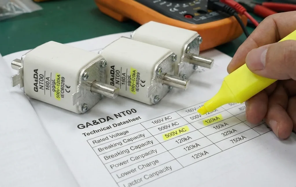
TABLE OF CONTENTS Engineers who understand fuse breaking capacity and voltage ratings can design safer, more reliable low‑voltage and PV systems. In any power distribution or PV combiner box, the fuse breaking capacity defines the maximum fault current the fuse can safely interrupt at its rated voltage without exploding or failing dangerously. In practical panel […]
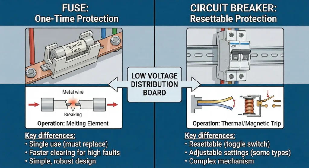
TABLE OF CONTENTS Fuse vs circuit breaker choices are at the heart of every low‑voltage protection design, from small consumer units to industrial switchboards and PV systems. Making the right fuse vs circuit breaker decision means understanding how each device behaves under overload and short‑circuit conditions, how it interacts with cables and loads, and what […]
Learn how to select an SPD backup fuse or circuit breaker for AC, DC and solar PV surge protection systems. Avoid common sizing and installation mistakes.
We use cookies to enhance your browsing experience, serve personalised ads or content, and analyse our traffic. By clicking "Accept All", you consent to our use of cookies.